A 36 Volt Electric Scooter Wiring Diagram is a comprehensive plan illustrating the connections between electrical components of a 36-volt electric scooter. For example, the diagram for a popular e-scooter brand may include the wiring of the battery, motor, controller, throttle, and brakes.
Understanding this diagram is crucial for troubleshooting malfunctions, installing new components, and ensuring safe and efficient operation. It enables users to identify and correct potential electrical issues promptly, minimizing downtime and enhancing the scooter’s longevity.
A significant historical development in electric scooter wiring is the adoption of standardized color-coding for electrical connections. This ensures consistency and reduces confusion when working with different scooter models, simplifies repairs and modifications, and enhances safety.
A 36 Volt Electric Scooter Wiring Diagram is a visual representation of the electrical connections within a 36-volt electric scooter. Understanding the key aspects of a wiring diagram is critical, as it provides guidance for troubleshooting, repair, and modification of the scooter’s electrical system.
- Components: Battery, motor, controller, throttle, brakes, lights
- Connections: Wires, terminals, connectors, fuses
- Layout: Physical arrangement of components and connections
- Color Coding: Standardized colors for different types of connections
- Symbols: Graphical representations of electrical components
- Circuitry: Flow of electricity through the system
- Troubleshooting: Identifying and resolving electrical issues
- Safety: Ensuring proper electrical connections to prevent hazards
- Modifications: Anpassungen for performance or functionality
These aspects provide a comprehensive framework for understanding the wiring diagram of a 36-volt electric scooter. By comprehending these aspects, users can maintain, repair, and modify their scooters safely and effectively, ensuring optimal performance and longevity.
Components
These components are the key elements of a 36 Volt Electric Scooter’s electrical system. The wiring diagram serves as a detailed roadmap, guiding the connections and interactions between these components.
The battery provides the electrical energy to power the motor. The controller regulates the flow of electricity from the battery to the motor, controlling the speed and torque of the scooter. The throttle is the user interface that allows the rider to control the speed of the scooter, sending signals to the controller to adjust the motor’s output.
The brakes are essential for safety, engaging when the rider applies pressure to the brake levers. They cut off the power supply to the motor and activate the braking system. The lights provide visibility during low-light conditions, ensuring the safety of the rider and others on the road.
Understanding the connections between these components through the wiring diagram empowers users to troubleshoot electrical issues, perform maintenance, and make modifications to enhance the scooter’s performance. It helps ensure the safe and efficient operation of the electric scooter, maximizing its lifespan and providing a reliable and enjoyable riding experience.
Connections
The connections within a 36 Volt Electric Scooter Wiring Diagram play a critical role in the scooter’s electrical system. Wires, terminals, connectors, and fuses are essential components that ensure the proper flow of electricity and protect the system from damage.
Wires serve as the pathways for electrical current to travel between components. Terminals provide secure connections between wires and other components, ensuring a reliable electrical contact. Connectors allow for easy disconnection and reconnection of components, facilitating maintenance and repairs. Fuses act as safety devices, protecting the electrical system from overcurrent situations that could lead to damage or fire.
Understanding these connections is crucial for troubleshooting electrical issues, performing maintenance, and making modifications to the scooter’s electrical system. The wiring diagram provides a detailed map of these connections, enabling users to identify and resolve problems quickly and efficiently. Proper connections ensure optimal performance, safety, and longevity of the electric scooter.
In conclusion, the connections in a 36 Volt Electric Scooter Wiring Diagram are a fundamental aspect of the scooter’s electrical system. Understanding these connections empowers users to maintain, repair, and modify their scooters safely and effectively, maximizing their performance and lifespan.
Layout
In a 36 Volt Electric Scooter Wiring Diagram, the layout of components and connections plays a critical role in the scooter’s functionality, safety, and maintainability. The physical arrangement of components determines the efficiency of electrical current flow, minimizes electromagnetic interference, and ensures optimal performance.
For instance, placing the battery close to the motor reduces energy loss due to wire resistance, leading to a more efficient use of power. Additionally, proper spacing between wires prevents short circuits and ensures reliable operation. The wiring diagram provides a clear visual representation of these arrangements, enabling users to understand the system’s layout and make informed decisions regarding modifications or repairs.
Understanding the layout of components and connections is essential for troubleshooting electrical issues. By analyzing the wiring diagram, users can identify potential problem areas, such as loose connections or damaged wires, and take appropriate corrective actions. This understanding also facilitates modifications to the electrical system, allowing users to upgrade components or add accessories while maintaining the scooter’s safety and performance.
In summary, the layout of components and connections in a 36 Volt Electric Scooter Wiring Diagram is a critical aspect that influences the scooter’s performance, safety, and maintainability. Understanding this layout empowers users to troubleshoot issues, make modifications, and optimize the scooter’s electrical system, ensuring a reliable and enjoyable riding experience.
Color Coding
Color coding plays a critical role in the 36 Volt Electric Scooter Wiring Diagram. Standardizing the colors for different types of connections ensures consistency, simplifies troubleshooting, and enhances safety. Each wire is assigned a specific color based on its function, making it easy to identify and trace connections throughout the electrical system.
For instance, in many wiring diagrams, red wires typically indicate positive connections, black wires represent negative connections, and green wires signify ground connections. This color-coding scheme is widely adopted across the industry, allowing technicians and riders to quickly identify and connect wires correctly, reducing the risk of errors and accidents.
Understanding color coding is essential for anyone working with a 36 Volt Electric Scooter Wiring Diagram. It enables them to identify and trace connections efficiently, troubleshoot electrical issues promptly, and make modifications or repairs safely. Proper color coding also facilitates the installation of additional components or accessories, ensuring compatibility and maintaining the scooter’s optimal performance.
In summary, color coding is a crucial aspect of 36 Volt Electric Scooter Wiring Diagrams, providing a standardized and simplified approach to electrical connections. Understanding and adhering to these color codes enhance safety, simplify troubleshooting, and empower users to maintain and modify their scooters effectively.
Symbols
In the context of a 36 Volt Electric Scooter Wiring Diagram, symbols play a vital role in representing various electrical components. These symbols provide a standardized visual language, enabling users to easily understand and interpret the complex electrical system of the scooter.
- Component Symbols: These represent individual electrical components such as batteries, motors, controllers, and switches. Each symbol is designed to convey the basic functionality and terminal connections of the component, simplifying the diagram.
- Connection Symbols: These indicate the electrical connections between components. Different symbols are used for different types of connections, such as wires, terminals, and connectors, ensuring clarity and reducing the risk of misinterpretation.
- Directional Symbols: Arrows or other symbols may be used to indicate the flow of electricity or data through the system. These symbols help users trace the path of electrical current and understand the sequence of operations.
- Ground Symbols: Ground symbols represent the electrical connection to the frame or chassis of the scooter. These symbols ensure proper grounding of the electrical system, which is crucial for safety and preventing electrical faults.
Understanding the symbols used in a 36 Volt Electric Scooter Wiring Diagram is essential for troubleshooting electrical issues, performing maintenance, and making modifications. By interpreting these symbols correctly, users can identify and resolve problems quickly and efficiently, ensuring the safe and optimal operation of their electric scooter.
Circuitry
Within the comprehensive framework of a 36 Volt Electric Scooter Wiring Diagram, the aspect of “Circuitry: Flow of electricity through the system” holds paramount importance, dictating the efficient and safe operation of the electric scooter. Understanding the intricate interplay of electrical components and the pathways of current flow is essential for troubleshooting, maintenance, and modifications.
- Electrical Components: The wiring diagram details the electrical components that constitute the scooter’s circuitry, including the battery, motor, controller, and switches. Each component plays a specific role in regulating and directing the flow of electricity.
- Current Pathways: The diagram illustrates the pathways through which electrical current travels, connecting the various components. Wires, terminals, and connectors establish these pathways, ensuring the smooth and efficient flow of electricity.
- Voltage and Current Regulation: The wiring diagram provides insights into the voltage and current regulation mechanisms employed within the circuitry. This information is crucial for understanding the scooter’s performance and identifying potential electrical issues.
- Grounding: The diagram indicates the grounding points within the circuitry, which are essential for safety and proper electrical functioning. Understanding the grounding scheme helps prevent electrical faults and ensures the safe operation of the scooter.
Comprehending the “Circuitry: Flow of electricity through the system” aspect of a 36 Volt Electric Scooter Wiring Diagram empowers users to diagnose and resolve electrical problems, perform maintenance tasks, and make informed modifications. It provides a roadmap for navigating the scooter’s electrical system, ensuring optimal performance, safety, and longevity.
Troubleshooting
The 36 Volt Electric Scooter Wiring Diagram serves as a valuable tool in troubleshooting various electrical issues. By understanding the diagram and its components, users can identify and resolve problems efficiently, ensuring the smooth operation of their electric scooter.
- Identifying Faulty Components: The wiring diagram helps identify potential faulty components by providing a clear visual representation of the electrical system. By analyzing the diagram, users can pinpoint specific components that may be causing electrical problems, such as loose connections, blown fuses, or damaged wires.
- Tracing Circuit Paths: The diagram allows users to trace the flow of electricity through the scooter’s circuits. This is crucial for identifying open or short circuits, which can disrupt the proper functioning of the electrical system. By tracing circuit paths, users can systematically troubleshoot and locate the source of electrical issues.
- Understanding Voltage and Current Flow: The wiring diagram provides insights into the voltage and current flow within the scooter’s electrical system. This information is essential for diagnosing and resolving electrical problems related to voltage drops, overcurrents, or ground faults. Understanding voltage and current flow empowers users to make informed decisions when troubleshooting electrical issues.
- Ensuring Proper Grounding: The wiring diagram indicates the grounding points within the electrical system, which are crucial for safety and proper electrical functioning. By ensuring proper grounding, users can prevent electrical faults, minimize interference, and maintain the overall stability of the scooter’s electrical system.
In conclusion, the aspect of “Troubleshooting: Identifying and resolving electrical issues” is intricately linked to the 36 Volt Electric Scooter Wiring Diagram. By leveraging the diagram as a guide, users can effectively troubleshoot electrical problems, identify faulty components, trace circuit paths, understand voltage and current flow, and ensure proper grounding. This comprehensive understanding empowers users to maintain and repair their electric scooters, ensuring optimal performance, safety, and longevity.
Safety
When navigating the intricacies of a 36 Volt Electric Scooter Wiring Diagram, prioritizing safety is paramount. Understanding the appropriate electrical connections is crucial for preventing hazards and ensuring the secure operation of the scooter. Several key facets contribute to this aspect of safety.
- Insulated Wires: Electrical wires must be properly insulated to prevent short circuits and potential fires. The wiring diagram specifies the type and gauge of insulation required for each wire, ensuring the appropriate level of protection.
- Secure Connections: Loose or improperly connected wires can lead to arcing, overheating, and electrical faults. The wiring diagram provides guidance on the correct techniques for securing connections, including the use of crimp connectors and solder joints.
- Grounding: Establishing a proper grounding system is essential for safety. The wiring diagram indicates the grounding points within the electrical system, ensuring that excess voltage is safely discharged to the frame of the scooter.
- Fuses and Circuit Breakers: Fuses and circuit breakers act as safety devices, protecting the electrical system from overcurrent conditions. The wiring diagram specifies the appropriate ratings and locations for these components, ensuring they operate effectively in the event of an electrical fault.
By adhering to the safety guidelines outlined in the 36 Volt Electric Scooter Wiring Diagram, users can minimize the risk of electrical hazards, ensuring the safe and reliable operation of their electric scooter. Properly insulated wires, secure connections, effective grounding, and appropriate protective devices work in concert to safeguard the electrical system and prevent potential accidents.
Modifications
In the realm of 36 Volt Electric Scooter Wiring Diagrams, modifications for performance or functionality play a pivotal role in tailoring the scooter to specific needs and preferences. These modifications involve alterations to the electrical system, leveraging the wiring diagram as a roadmap to achieve desired outcomes.
Whether seeking enhanced acceleration, extended range, or custom lighting configurations, modifications hinge upon a thorough understanding of the wiring diagram. By analyzing the diagram’s layout, component interconnections, and voltage/current flow, informed decisions can be made regarding which modifications are feasible and how they will impact the scooter’s performance.
Real-life examples of modifications include upgrading the battery to a higher voltage or capacity for increased range, installing a performance controller to optimize motor output for improved acceleration, or adding auxiliary lighting systems for enhanced visibility and style. Each modification requires careful consideration of the wiring diagram to ensure compatibility and safe implementation.
Understanding the connection between modifications and the wiring diagram empower users to make informed choices, customize their scooters to suit their individual needs, and maximize their riding experience. It also enables them to identify potential pitfalls and ensure modifications are executed safely and effectively.


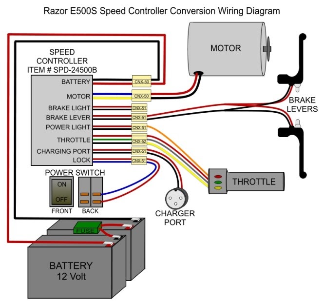

![[DIAGRAM] 36 Volt Electric Scooter Controller Wiring Diagram](https://i0.wp.com/img.auctiva.com/imgdata/1/4/5/3/7/1/8/webimg/636194117_o.jpg?w=665&ssl=1)

Related Posts


