A 3.5mm Jack Wiring Diagram refers to the standardized layout and connection of five conductors within a 3.5mm audio jack, typically used for transmitting audio and video signals. For instance, the left audio channel is connected to the tip contact, while the right audio channel is connected to the ring contact.
Understanding this wiring diagram is crucial for audio-related projects and repairs, ensuring proper signal transmission. It provides a clear visual representation of the conductor connections, aiding in the identification of issues and the correct assembly of audio components.
The 3.5mm jack has become ubiquitous in personal electronics due to its compact size and versatility, serving as a standard interface for headphones, microphones, and other audio devices. Its historical development has played a significant role in the widespread adoption of portable audio technology.
The 3.5mm jack wiring diagram is a crucial aspect of audio engineering, as it outlines the standardized layout and connection of conductors within the jack, ensuring proper signal transmission between audio devices. Understanding the various aspects of this wiring diagram is essential for troubleshooting, repair, and the development of audio systems.
- Standardization: Adherence to industry-wide specifications for compatibility.
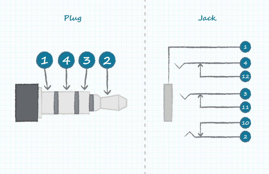
- Conductor layout: Arrangement of conductors within the jack, including left and right audio channels.
- Connection types: Soldering, crimping, or other methods used to connect conductors.
- Signal flow: Understanding the path of audio signals through the wiring diagram.
- Troubleshooting: Identifying and resolving issues related to wiring, such as shorts or breaks.
- Compatibility: Ensuring compatibility between devices with different jack configurations.
- Audio quality: Impact of wiring quality on the fidelity and clarity of audio signals.
- Safety: Adhering to safety guidelines to prevent electrical hazards.
These aspects provide a comprehensive understanding of the 3.5mm jack wiring diagram, enabling technicians, engineers, and hobbyists to effectively work with audio systems. By considering the standardization, conductor layout, and other key aspects, they can ensure reliable signal transmission, troubleshoot issues, and develop high-quality audio products.
Standardization
Standardization plays a critical role in the 3.5mm jack wiring diagram. Adherence to industry-wide specifications ensures compatibility between different audio devices, allowing for seamless signal transmission and interchangeability of components. Without standardization, each manufacturer could create proprietary wiring diagrams, leading to incompatibility and confusion.
The 3.5mm jack wiring diagram defines the arrangement of conductors within the jack, including the tip, ring, sleeve, and ground contacts. Each contact serves a specific purpose, such as carrying the left or right audio channel, or providing a ground reference. By adhering to the standardized wiring diagram, manufacturers can ensure that their devices will work with any other device that uses a 3.5mm jack.
Real-life examples of standardization in the 3.5mm jack wiring diagram include the use of color-coded wires to identify each conductor, and the specification of the jack’s dimensions and tolerances. These standards make it easy for technicians to identify and connect the correct wires, reducing errors and ensuring reliable performance.
Understanding the 3.5mm jack wiring diagram and its standardization is essential for anyone working with audio systems. It enables technicians to troubleshoot problems, repair devices, and develop new audio products. By adhering to industry-wide specifications, manufacturers can ensure that their products are compatible with a wide range of devices, providing consumers with a seamless and reliable audio experience.
Conductor layout
The conductor layout of a 3.5mm jack wiring diagram refers to the specific arrangement and organization of conductors within the jack. Conductors are the individual wires or pathways that carry electrical signals, and in the context of a 3.5mm jack, they are responsible for transmitting audio signals between devices.
The conductor layout plays a critical role in ensuring proper signal transmission and audio quality. Each conductor is assigned a specific function, such as carrying the left or right audio channel, providing a ground reference, or supplying power. By adhering to a standardized conductor layout, manufacturers can ensure that their devices are compatible with a wide range of other devices that use 3.5mm jacks.
A real-life example of the conductor layout in a 3.5mm jack wiring diagram is the use of color-coded wires to identify each conductor. The left audio channel is typically carried by a red wire, the right audio channel by a white or green wire, and the ground reference by a black or bare wire. This color-coding makes it easy for technicians to identify and connect the correct wires, reducing errors and ensuring reliable performance.
Understanding the conductor layout of a 3.5mm jack wiring diagram is essential for anyone working with audio systems. It enables technicians to troubleshoot problems, repair devices, and develop new audio products. By adhering to industry-wide standards and understanding the function of each conductor, technicians can ensure that audio signals are transmitted properly, resulting in clear and high-quality audio.
Connection types
Connection types play a critical role in the effectiveness and reliability of a 3.5mm jack wiring diagram. The choice of connection method, such as soldering, crimping, or other techniques, directly impacts the quality of the electrical connection between the conductors and the jack contacts. Proper connection ensures efficient signal transmission and prevents intermittent or degraded audio performance.
Soldering is a widely used method for connecting conductors in a 3.5mm jack wiring diagram due to its strong and durable bond. It involves melting a solder alloy onto the conductor and jack contact, creating a permanent electrical and mechanical joint. Soldering requires specialized equipment and skills to execute correctly, but it provides a highly reliable connection that can withstand environmental factors such as vibration and temperature fluctuations.
Crimping is another common connection method that utilizes a crimping tool to compress a metal sleeve or ferrule onto the conductor and jack contact. Crimping creates a secure mechanical connection that is less prone to failure than a simple twist or wrap. However, crimping requires precise crimping tools and ferrules to ensure a proper connection and avoid damage to the conductor or jack contacts.
Understanding the different connection types and their suitability for specific applications is crucial for working with 3.5mm jack wiring diagrams. By selecting the appropriate connection method and executing it correctly, technicians can ensure reliable signal transmission and enhance the overall performance of audio systems.
Signal flow
Signal flow, the path audio signals take through a 3.5mm jack wiring diagram, is critical for ensuring proper transmission and sound quality. Understanding this flow involves examining the components, connections, and signal routing within the diagram.
-
Conductor Roles
Each conductor in the diagram has a specific role, such as carrying the left or right audio channel, providing a ground reference, or supplying power. Understanding these roles ensures proper signal routing and prevents interference.
-
Contact Points
Signals flow through specific contact points within the jack, including the tip, ring, sleeve, and ground contacts. Identifying these contact points is essential for making correct connections and maintaining signal integrity.
-
Signal Routing
The wiring diagram specifies the path that signals take through the jack, ensuring they reach the intended destination without crosstalk or signal loss. Proper signal routing optimizes audio quality and functionality.
-
Grounding
Grounding plays a crucial role in maintaining signal integrity and preventing noise. The wiring diagram defines the grounding scheme, ensuring that all components are properly grounded to eliminate unwanted electrical interference.
Understanding signal flow through a 3.5mm jack wiring diagram is essential for troubleshooting, repair, and design. By analyzing the components, connections, and signal routing, technicians can diagnose and resolve audio issues, ensuring optimal sound performance in various electronic devices.
Troubleshooting
In the context of 3.5mm jack wiring diagrams, troubleshooting plays a vital role in maintaining optimal audio performance and resolving common issues. Wiring-related problems, such as shorts or breaks, can significantly impact signal transmission and cause audible distortions or complete loss of audio. Understanding the wiring diagram becomes crucial for effective troubleshooting and repair.
A short circuit occurs when an unintended electrical path forms between two conductors, causing a sudden drop in resistance and potentially damaging connected components. Breaks, on the other hand, result in an open circuit where the electrical path is disrupted, leading to a loss of signal. Identifying the exact location of these faults within the wiring diagram is essential for targeted repairs.
Real-life examples of troubleshooting wiring issues in 3.5mm jack wiring diagrams include:
- Intermittent audio cutting out due to a loose or broken connection at the solder joint between a conductor and jack contact.
- Continuous buzzing or humming sound caused by a short circuit between the ground and audio conductors.
- Complete loss of audio in one channel due to a break in the corresponding audio conductor.
By analyzing the wiring diagram and using appropriate testing tools, such as a multimeter, technicians can pinpoint the faulty connection or break, enabling efficient repairs. Understanding the circuit’s layout and signal flow allows them to isolate the problem and avoid unnecessary component replacements.
Compatibility
Within the realm of 3.5mm jack wiring diagrams, compatibility plays a pivotal role in facilitating seamless connectivity and signal transmission between various audio devices. Ensuring compatibility addresses the challenge of enabling devices with potentially different jack configurations to communicate effectively.
-
Adapter Compatibility
Adapters serve as intermediaries, allowing devices with incompatible jack configurations to connect. These adapters bridge the physical and electrical differences between jacks, ensuring signal integrity and functionality.
-
Industry Standards
Adherence to industry-defined standards, such as the Consumer Electronics Association (CEA) color-coding scheme, promotes compatibility. By following these standards, manufacturers ensure that devices with different brands and models can be interconnected seamlessly.
-
Universal Jack Design
The adoption of universal jack designs, such as the 3.5mm TRRS (Tip, Ring, Ring, Sleeve) connector, enhances compatibility. This standardized design accommodates various audio and microphone configurations, allowing for versatile device interconnections.
-
Multi-Device Connectivity
Compatibility considerations extend to multi-device connectivity scenarios. Devices like smartphones, laptops, and audio interfaces often require seamless audio signal exchange. Ensuring compatibility enables users to connect multiple devices with different jack configurations, creating flexible and adaptable audio setups.
In essence, compatibility in 3.5mm jack wiring diagrams is crucial for enabling interoperability between devices, facilitating seamless audio signal transmission, and enhancing the user experience. By considering factors such as adapter compatibility, industry standards, universal jack designs, and multi-device connectivity, engineers and users can ensure effective and reliable audio connections across a diverse range of devices.
Audio quality
Within the realm of 3.5mm jack wiring diagrams, audio quality takes center stage, as it profoundly influences the fidelity and clarity of transmitted audio signals. The quality of the wiring employed directly impacts the integrity of the signal, affecting various aspects of the listening experience.
-
Conductor Material and Purity
The choice of conductor material, such as copper or silver, and its purity level significantly influence signal quality. Higher-purity conductors minimize resistance and reduce signal distortion, resulting in enhanced clarity and reduced noise.
-
Wire Gauge and Insulation
The wire gauge, or thickness, affects the current-carrying capacity and signal loss. Thicker gauge wires offer lower resistance, while proper insulation prevents signal degradation due to electromagnetic interference.
-
Soldering and Connections
The quality of soldering and connections at the jack contacts is crucial. Poor soldering joints or loose connections can introduce noise, distortion, and intermittent signal dropouts.
-
Shielding and Grounding
Proper shielding and grounding techniques minimize external noise and hum, ensuring a clean and quiet audio signal. Effective grounding provides a reference point for the signal, reducing unwanted electrical interference.
Understanding the impact of wiring quality on audio quality empowers audio enthusiasts, engineers, and technicians to make informed choices when designing, installing, or troubleshooting 3.5mm jack wiring diagrams. By prioritizing high-quality wiring materials, meticulous soldering, and proper shielding, they can ensure the faithful reproduction and clarity of audio signals, elevating the overall listening experience.
Safety
When working with 3.5mm jack wiring diagrams, safety is of paramount importance to prevent electrical hazards and ensure the well-being of individuals. Electrical hazards can arise from improper handling, incorrect connections, or faulty components, leading to electric shock, fire, or equipment damage.
Safety guidelines provide a framework for safe practices when dealing with electrical systems, including 3.5mm jack wiring diagrams. These guidelines address various aspects, such as proper grounding techniques, insulation requirements, and appropriate handling procedures. By adhering to these guidelines, individuals can minimize the risk of electrical accidents and protect themselves and others from harm.
Real-life examples of safety considerations within 3.5mm jack wiring diagrams include ensuring that the jack is securely fastened to prevent accidental disconnections, using insulated wires to avoid short circuits, and employing proper soldering techniques to create reliable electrical connections. Furthermore, understanding the current and voltage limitations of the system is crucial to select appropriate components and prevent overloading.
The practical applications of understanding the connection between safety and 3.5mm jack wiring diagrams extend to various fields. In the consumer electronics industry, manufacturers incorporate safety features into their products, such as polarized plugs and built-in surge protection, to enhance user safety. In professional audio setups, technicians rely on safety guidelines to ensure proper installation and maintenance of audio systems, minimizing the risk of electrical hazards during live performances or recording sessions.
In summary, safety plays a critical role in 3.5mm jack wiring diagrams, guiding individuals towards safe practices when dealing with electrical systems. Adhering to safety guidelines helps prevent electrical hazards, ensuring the well-being of users and the integrity of equipment. Understanding the connection between safety and 3.5mm jack wiring diagrams is essential for responsible and effective work in various fields.


Related Posts


