A 3-way dimmer switch wiring schematic illustrates the electrical connections for controlling the brightness of a light fixture from two different locations. It consists of two 3-way switches that are connected to the light fixture and to each other, allowing for independent control of the light from each switch location.
This wiring schematic is commonly used in hallways, stairwells, and other areas where it is convenient to control lighting from multiple points. Its relevance lies in providing flexible lighting control and enhancing convenience in various architectural settings. The benefits include energy efficiency by enabling users to adjust the brightness of the light to suit their needs, as well as aesthetic control by creating desired lighting ambiance.
A key historical development in 3-way dimmer switch wiring is the introduction of electronic dimmers that offer advanced features. These dimmers provide smooth and flicker-free dimming, compatibility with a wider range of light sources, and preset lighting scenes for added convenience.
The 3-way dimmer switch wiring schematic is a crucial aspect of electrical wiring, enabling the control of lighting from multiple locations. Understanding its key aspects is essential for proper installation, maintenance, and troubleshooting.
- Circuit Design: Understanding the electrical circuit design is paramount, including the connection of switches, wires, and the light fixture.
- Switch Compatibility: Choosing compatible 3-way switches is vital for proper operation and safety.
- Wiring Configuration: The specific wiring configuration, involving the connection of wires to terminals, ensures correct functionality.
- Neutral Wire Requirement: Identifying and utilizing the neutral wire is essential for successful dimming operation.
- Power Source: Determining the appropriate power source, whether line voltage or low voltage, is crucial for system compatibility.
- Dimmer Type: Selecting the correct dimmer type, such as incandescent, LED, or electronic, ensures compatibility with the light fixture and desired dimming range.
- Load Capacity: Calculating the total load, considering the wattage of connected lights, is essential to prevent overloading and potential hazards.
- Switch Location Planning: Planning the placement of 3-way switches for optimal convenience and accessibility is important.
- Code Compliance: Adhering to electrical codes and regulations ensures safety and proper installation.
- Troubleshooting: Understanding common troubleshooting techniques helps resolve issues and maintain functionality.
These key aspects provide a comprehensive understanding of 3-way dimmer switch wiring schematics. Proper consideration of these aspects ensures efficient and reliable lighting control, enhances safety, and complies with electrical standards.
Circuit Design
In the context of 3-way dimmer switch wiring schematics, understanding the electrical circuit design is of utmost importance. The schematic outlines the connections between switches, wires, and the light fixture, forming a complete electrical circuit that enables lighting control from multiple locations. The proper design and execution of this circuit are crucial for the safe and effective operation of the dimmer switch.
For instance, incorrect wiring of the switches or improper connection of wires can result in malfunctioning of the dimmer switch, flickering lights, or even electrical hazards. Therefore, a clear understanding of the circuit design, including the identification of the line, load, and neutral wires, is essential for successful installation and maintenance of the 3-way dimmer switch wiring schematic.
In practical applications, circuit design plays a vital role in ensuring the desired functionality and efficiency of the lighting system. By carefully planning and executing the circuit design, electricians can optimize the performance of the dimmer switch, ensuring smooth dimming operation, preventing overloading, and enhancing the overall user experience.
In conclusion, a thorough understanding of circuit design is paramount for the proper functioning of 3-way dimmer switch wiring schematics. It forms the foundation for safe and reliable lighting control, enabling the creation of flexible and convenient lighting environments in various architectural settings.
Switch Compatibility
In the context of 3-way dimmer switch wiring schematics, switch compatibility plays a critical role in ensuring the safe and effective operation of the lighting system. Choosing compatible 3-way switches involves selecting switches that are designed to work together and with the specific type of dimmer being used. Compatibility issues can lead to a range of problems, from flickering lights to electrical hazards.
- Switch Type: 3-way switches come in different types, such as mechanical and electronic. It is essential to choose switches that are compatible with the dimmer type being used. Mechanical switches are typically used with incandescent and halogen bulbs, while electronic switches are compatible with a wider range of lighting types, including LEDs and CFLs.
- Voltage Rating: The voltage rating of the switch must match the voltage of the electrical system. Using a switch with an incorrect voltage rating can lead to overheating, damage to the switch, or even electrical shock.
- Amperage Rating: The amperage rating of the switch must be sufficient to handle the total load of the connected lights. Exceeding the amperage rating of the switch can lead to overheating and potential fire hazards.
- Manufacturer Compatibility: Some dimmer manufacturers recommend using switches from the same manufacturer to ensure compatibility. This is especially important for electronic dimmers, which may require specific switch characteristics to function properly.
Choosing compatible 3-way switches is crucial for the safety and proper operation of the lighting system. By carefully selecting switches that are compatible with the dimmer and electrical system, electricians can ensure reliable and efficient lighting control, avoiding potential hazards and enhancing the overall user experience.
Wiring Configuration
In the context of 3-way dimmer switch wiring schematics, wiring configuration plays a crucial role in ensuring the safe and effective operation of the lighting system. Wiring configuration involves the specific connection of wires to terminals on the switches, dimmer, and light fixture. Correct wiring is essential for completing the electrical circuit and enabling the dimmer switch to control the light fixture properly.
For instance, incorrect wiring of the wires to the terminals can result in the dimmer switch not functioning correctly, flickering lights, or even electrical hazards. Therefore, a clear understanding of the wiring configuration, including the identification of the line, load, and neutral wires, is essential for successful installation and maintenance of the 3-way dimmer switch wiring schematic.
In practical applications, wiring configuration is a critical aspect of electrical work. Electricians must carefully follow the wiring schematic to ensure that the wires are connected to the correct terminals. This attention to detail is particularly important in the context of 3-way dimmer switches, as incorrect wiring can lead to safety issues or damage to the equipment.
In conclusion, wiring configuration is a fundamental component of 3-way dimmer switch wiring schematics. Proper wiring ensures the safe and reliable operation of the lighting system, enabling the control of lighting from multiple locations. Understanding and adhering to the correct wiring configuration is essential for electricians and homeowners alike, contributing to the overall safety and functionality of the electrical system.
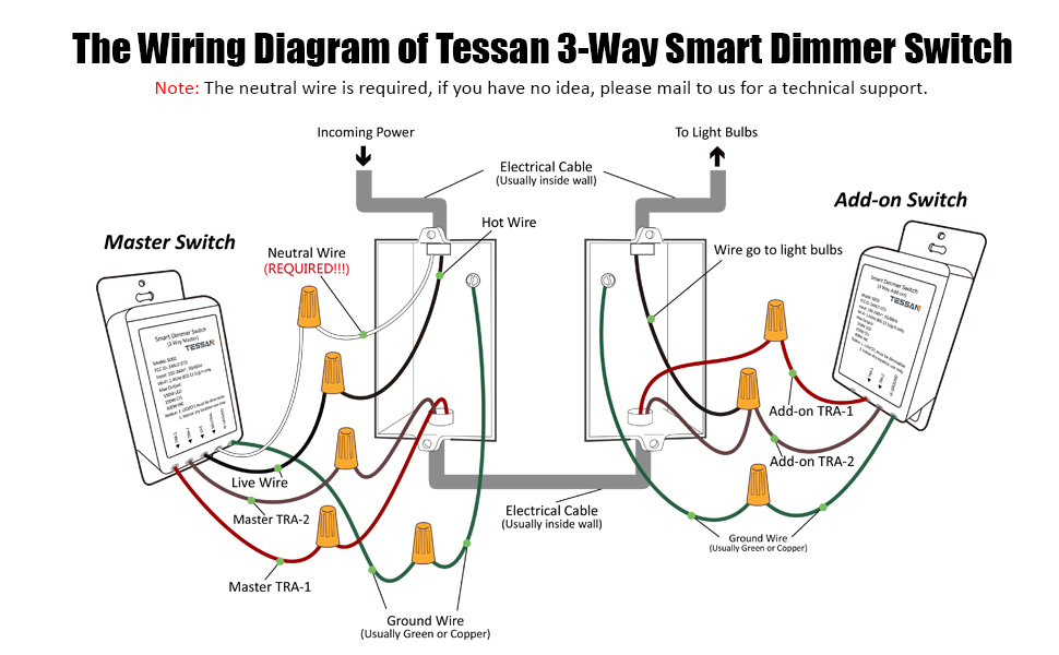
Neutral Wire Requirement
In the context of 3-way dimmer switch wiring schematics, understanding the neutral wire requirement is crucial for ensuring the safe and effective operation of the lighting system. The neutral wire provides a return path for the electrical current, completing the circuit and enabling the dimmer switch to control the light fixture properly.
Without a neutral wire, the dimmer switch may not function correctly, flickering lights, or even posing electrical hazards. Therefore, identifying and utilizing the neutral wire is a critical component of 3-way dimmer switch wiring schematics, ensuring the reliable and efficient control of lighting from multiple locations.
In practical applications, electricians must carefully identify the neutral wire, typically white or gray in color, and connect it to the designated terminal on the dimmer switch and light fixture. Failure to connect the neutral wire can lead to a range of issues, including dimmer switch malfunction, flickering lights, and potential electrical hazards.
Understanding the neutral wire requirement is essential for both the design and installation of 3-way dimmer switch wiring schematics. By adhering to the correct wiring configuration and ensuring a proper connection to the neutral wire, electricians can ensure the safe and reliable operation of the lighting system, contributing to the overall functionality and safety of the electrical system.
Power Source
In the context of 3-way dimmer switch wiring schematics, selecting the appropriate power source is a critical consideration that directly affects system compatibility and performance. The power source choice, whether line voltage or low voltage, has implications for various aspects of the wiring schematic design.
- Voltage Level: Line voltage, typically 120V or 240V, is used for directly powering lighting fixtures. Low voltage, usually ranging from 12V to 24V, requires a transformer to convert the line voltage to the lower voltage level.
- Compatibility: The type of dimmer switch and lighting fixtures must be compatible with the chosen power source. Line voltage dimmers are designed for use with line voltage fixtures, while low voltage dimmers are specifically designed for low voltage fixtures.
- Safety: Line voltage systems pose a higher risk of electrical shock and require proper safety measures, such as proper insulation and grounding. Low voltage systems are generally safer, but precautions should still be taken to prevent potential hazards.
- Efficiency: Low voltage systems can offer improved energy efficiency compared to line voltage systems, particularly when combined with LED lighting fixtures.
Understanding the power source requirements and compatibility is essential for designing and installing a safe and effective 3-way dimmer switch wiring schematic. Careful consideration of the voltage level, compatibility, safety implications, and energy efficiency aspects ensures optimal system performance and user safety.
Dimmer Type
In the context of 3-way dimmer switch wiring schematics, selecting the correct dimmer type is crucial for ensuring compatibility with the light fixture and achieving the desired dimming range. Different types of dimmers are designed to work with specific types of lighting fixtures and dimming technologies. Understanding the characteristics and limitations of each dimmer type is essential for a successful and safe installation.
-
Incandescent Dimmers:
Incandescent dimmers are designed to control the brightness of incandescent light bulbs. They work by varying the amount of voltage supplied to the bulb, resulting in a smooth and flicker-free dimming experience. Incandescent dimmers are typically the most affordable and widely available option, but they are not compatible with other lighting technologies, such as LEDs or CFLs.
-
LED Dimmers:
LED dimmers are specifically designed to work with LED light bulbs. They use advanced electronic circuitry to regulate the current and voltage supplied to the LED bulb, ensuring flicker-free dimming and long bulb life. LED dimmers are more expensive than incandescent dimmers, but they offer better energy efficiency and compatibility with a wider range of LED bulbs.
-
Electronic Dimmers:
Electronic dimmers are a versatile option that can be used with incandescent, halogen, and dimmable CFL bulbs. They offer a wide dimming range and can be programmed to create custom dimming profiles. Electronic dimmers are more expensive than incandescent dimmers but provide greater flexibility and control.
-
Smart Dimmers:
Smart dimmers are advanced electronic dimmers that can be controlled remotely using a smartphone app or voice assistant. They offer a wide range of features, such as scheduling, dimming presets, and compatibility with smart home systems. Smart dimmers are the most expensive option, but they provide the ultimate in convenience and control.
Choosing the correct dimmer type is essential for a safe and satisfactory lighting control experience. Considering the type of lighting fixtures and the desired dimming range is crucial to ensure compatibility and optimal performance. By understanding the differences between incandescent, LED, electronic, and smart dimmers, electricians and homeowners can make informed decisions that enhance the functionality and ambiance of their lighting systems.
Load Capacity
Within the context of 3-way dimmer switch wiring schematics, load capacity plays a crucial role in ensuring the safe and efficient operation of the lighting system. Load capacity refers to the maximum amount of electrical power that a dimmer switch can handle without overloading, which can lead to overheating, damage to the dimmer switch, and potential fire hazards.
-
Wattage Calculation:
Calculating the total wattage of the connected lights is essential to determine the load capacity requirement. Each light fixture has a specified wattage rating, and the total load is the sum of the wattage ratings of all the connected lights. Exceeding the load capacity of the dimmer switch can lead to overloading and potential hazards.
-
Dimmer Switch Rating:
Dimmer switches have a specified wattage rating that indicates the maximum load they can handle. It is important to choose a dimmer switch with a wattage rating that is equal to or greater than the total wattage of the connected lights.
-
Overloading Risks:
Overloading a dimmer switch can have serious consequences. Overheating can cause damage to the dimmer switch’s internal components, leading to malfunction or failure. In extreme cases, overloading can also pose a fire hazard.
-
Safety Precautions:
To ensure safety, it is essential to adhere to the load capacity specifications of the dimmer switch and to avoid overloading. Proper installation and maintenance, including regular inspection and replacement of worn-out components, are also important for maintaining the integrity of the wiring schematic and preventing potential hazards.
Understanding and considering load capacity in 3-way dimmer switch wiring schematics is crucial for the safe and reliable operation of the lighting system. By carefully calculating the total wattage of the connected lights and selecting a dimmer switch with an appropriate wattage rating, electricians and homeowners can prevent overloading and potential hazards, ensuring the longevity and functionality of the lighting system.
Switch Location Planning
Within the context of 3-way dimmer switch wiring schematics, switch location planning plays a critical role in ensuring the convenient and accessible control of lighting from multiple locations. Careful consideration of switch placement optimizes the user experience and enhances the overall functionality of the lighting system.
-
Accessibility:
Switch placement should prioritize accessibility for users of all ages and abilities. Switches should be positioned at a comfortable height, typically around 48 inches from the floor, and within easy reach from frequently used areas, such as doorways and hallways.
-
Traffic Flow:
Consider the natural flow of traffic when planning switch locations. Switches should be placed where they can be easily accessed without obstructing pathways or creating safety hazards. This is particularly important in high-traffic areas, such as hallways and entryways.
-
Visual Cues:
Switches should be visually noticeable to prevent confusion or difficulty in locating them. This can be achieved through the use of contrasting colors, illuminated switches, or clear labeling. Proper visibility ensures quick and intuitive control of lighting.
-
Aesthetic Considerations:
In addition to functionality, switch placement should also consider aesthetic appeal. Switches should complement the dcor of the room and not detract from the overall design scheme. This can involve choosing switches that match the wall color, opting for decorative switch plates, or concealing switches in inconspicuous locations.
Effective switch location planning integrates these factors to create a lighting system that is both convenient and aesthetically pleasing. By carefully considering accessibility, traffic flow, visual cues, and aesthetic considerations, electricians and homeowners can optimize the user experience and enhance the functionality of any space.
Code Compliance
Within the context of 3-way dimmer switch wiring schematics, code compliance plays a crucial role in ensuring the safety and integrity of the electrical system. Electrical codes and regulations establish minimum safety standards for the installation and maintenance of electrical wiring, including the use of dimmer switches.
Adhering to code compliance in 3-way dimmer switch wiring schematics involves following specific guidelines related to wire sizing, circuit protection, and switch placement. Proper wire sizing ensures that the wires can safely carry the electrical current without overheating or causing a fire hazard. Circuit protection devices, such as fuses or circuit breakers, are essential for preventing electrical overloads and short circuits that could damage the dimmer switch or other components.
Real-life examples of code compliance in 3-way dimmer switch wiring schematics include the use of appropriately sized wires, such as 14-gauge or 12-gauge wire for typical lighting circuits. Additionally, the installation of dimmer switches in accordance with electrical codes ensures that they are properly grounded and connected to the correct circuit.
The practical significance of understanding code compliance lies in the prevention of electrical hazards and accidents. By adhering to electrical codes, electricians and homeowners can minimize the risk of electrical fires, shocks, or other dangerous situations. Code compliance also contributes to the overall reliability and efficiency of the electrical system, ensuring that dimmer switches and other electrical components function properly.
Troubleshooting
In the context of 3-way dimmer switch wiring schematics, troubleshooting plays a critical role in maintaining the proper operation and functionality of the lighting system. By understanding common troubleshooting techniques, electricians and homeowners can diagnose and resolve issues, ensuring a safe and reliable lighting system.
-
Identifying Faulty Components:
Troubleshooting involves identifying faulty components or connections within the wiring schematic. This may include checking for loose wires, damaged switches, or malfunctioning dimmers. By systematically testing and isolating potential issues, electricians can pinpoint the root cause of the problem.
-
Real-Life Examples:
Common troubleshooting scenarios include flickering lights, dimmers not responding properly, or lights not turning on at all. Each of these issues may have specific causes that require targeted troubleshooting techniques to resolve.
-
Safety Considerations:
Troubleshooting electrical systems, including 3-way dimmer switch wiring schematics, requires adherence to safety protocols. This includes using proper tools, isolating the circuit, and following electrical codes to minimize the risk of shock or electrical hazards.
-
Implications for Maintenance:
Regular troubleshooting and maintenance are essential for the long-term functionality of 3-way dimmer switch wiring schematics. By proactively identifying and resolving potential issues, electricians can prevent minor problems from escalating into more significant electrical faults.
Understanding common troubleshooting techniques empowers electricians and homeowners to effectively maintain and repair 3-way dimmer switch wiring schematics. By employing a systematic approach to problem-solving, identifying faulty components, and addressing safety concerns, they can ensure the reliable and safe operation of the lighting system.


Related Posts


