A 3 Position Rotary Switch Wiring Diagram visually represents the electrical connections and configuration of a 3 position rotary switch. It provides a clear and comprehensive guide for installing, troubleshooting, and understanding how the switch operates.
3 Position Rotary Switches play a crucial role in controlling electrical circuits. Their primary function is to effortlessly toggle between three distinct circuit configurations. They offer a robust and reliable solution in applications where multiple circuit paths need to be managed.
In the article that follows, we will delve deeper into the intricate details of 3 Position Rotary Switches. We will explore their anatomy, delve into their various operating principles, and uncover their widespread applications. Through this exploration, we aim to provide a comprehensive understanding of these versatile electrical components.
3 Position Rotary Switch Wiring Diagrams play a critical role in electrical systems, providing a roadmap for understanding and manipulating circuit configurations. To fully comprehend these diagrams, it is essential to examine their key aspects:
- Circuit Configuration: Illustrates how the switch connects and disconnects different parts of the circuit.
- Terminal Designations: Identifies the specific terminals on the switch and their corresponding functions.
- Switch Positions: Depicts the various positions of the switch and the resulting circuit configurations.
- Electrical Ratings: Specifies the maximum voltage and current that the switch can handle safely.
- Wiring Connections: Shows how the switch should be connected to other components in the circuit.
- Switch Type: Indicates whether the switch is momentary or maintained, affecting its behavior.
- Panel Mounting: Details the method used to mount the switch on a panel or enclosure.
- Terminal Arrangement: Describes the physical layout of the terminals on the switch.
- Switch Function: Explains the intended purpose of the switch in the circuit.
Understanding these aspects empowers electrical professionals to effectively install, maintain, and troubleshoot 3 Position Rotary Switches. These switches find applications in diverse industries, including power distribution, industrial control, and instrumentation.
Circuit Configuration
In the context of a 3 Position Rotary Switch Wiring Diagram, circuit configuration is paramount. It serves as the blueprint for understanding how the switch operates and how it alters the flow of electricity within a circuit. By examining the circuit configuration, electricians can determine which terminals are connected and disconnected in each switch position.
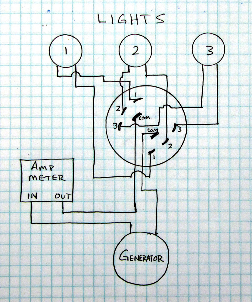
For instance, consider a 3 Position Rotary Switch used to control a lighting system. The wiring diagram would illustrate how the switch connects the power source to different light fixtures, depending on the switch position. In one position, the switch might connect the power to a ceiling light, while in another position, it might connect to a table lamp. Understanding the circuit configuration is crucial for ensuring that the switch functions as intended and that the lighting system operates safely.
The ability to visualize and analyze circuit configurations empowers electricians to troubleshoot problems and make informed decisions about switch selection and installation. It enables them to predict the behavior of the circuit and identify potential issues before they arise. Overall, a deep understanding of circuit configuration is indispensable for effective electrical design, maintenance, and repair.
Terminal Designations
Within the context of a 3 Position Rotary Switch Wiring Diagram, terminal designations hold paramount importance. They serve as the roadmap for understanding the switch’s electrical connections and ensuring its proper installation and operation. By clearly identifying the specific terminals on the switch and their corresponding functions, these designations enable electricians to confidently navigate the wiring process and achieve the desired circuit configuration.
- Terminal Identification: Each terminal on the switch is assigned a unique identifier, typically a number or letter. This identification allows electricians to easily distinguish between terminals and ensures accurate wiring connections.
- Function Definition: The wiring diagram specifies the function of each terminal. This information indicates whether the terminal is used for power input, output, or other specific purposes. Understanding the terminal functions is crucial for establishing the correct circuit connections.
- Terminal Arrangement: The diagram illustrates the physical arrangement of the terminals on the switch. This information guides electricians in connecting wires to the correct terminals and ensuring proper spacing to avoid short circuits.
- Terminal Ratings: The wiring diagram may also specify the electrical ratings of each terminal, such as the maximum voltage and current it can handle. This information ensures that the switch is used within its safe operating limits.
By carefully following the terminal designations provided in the wiring diagram, electricians can ensure that the 3 Position Rotary Switch is wired correctly, minimizing the risk of electrical hazards and ensuring the reliable operation of the circuit. These designations serve as a vital reference point throughout the installation, troubleshooting, and maintenance processes.
Switch Positions
Within the context of a 3 Position Rotary Switch Wiring Diagram, the switch positions play a critical role in understanding and controlling the circuit’s behavior. These diagrams illustrate the various positions of the switch and the corresponding circuit configurations that result from each position. This information is crucial for electricians and engineers to properly install and operate the switch, ensuring the desired functionality and safety of the circuit.
The switch positions are typically represented by numbers or symbols on the wiring diagram. Each position corresponds to a specific arrangement of internal contacts within the switch, which in turn determines which terminals are connected or disconnected. By understanding the switch positions and their corresponding circuit configurations, electricians can predict how the circuit will behave in each position.
For example, consider a 3 Position Rotary Switch used to control a fan’s speed. The wiring diagram would show three switch positions: low, medium, and high. In the low position, the switch might connect the fan motor to a lower voltage source, resulting in a slower fan speed. In the medium position, the switch might connect the motor to a higher voltage source, resulting in a medium fan speed. And in the high position, the switch might connect the motor to the highest voltage source, resulting in the highest fan speed.
Understanding the switch positions and their corresponding circuit configurations is essential for troubleshooting and maintaining electrical systems. By analyzing the wiring diagram, electricians can identify the cause of a malfunction and determine the necessary repairs. Additionally, this understanding enables engineers to design circuits that meet specific requirements and optimize performance.
In summary, the switch positions depicted on a 3 Position Rotary Switch Wiring Diagram are a critical component for understanding, installing, and maintaining electrical circuits. By analyzing the switch positions and their corresponding circuit configurations, electricians and engineers can ensure the safe and efficient operation of electrical systems.
Electrical Ratings
Within the context of a 3 Position Rotary Switch Wiring Diagram, electrical ratings hold paramount importance. They define the operational limits of the switch, ensuring safe and reliable performance within a circuit. These ratings encompass two key aspects: maximum voltage and maximum current.
- Voltage Rating: The voltage rating specifies the maximum voltage that the switch can withstand without compromising its insulation or causing electrical breakdown. Exceeding the voltage rating can lead to arcing, insulation failure, and even catastrophic switch failure.
- Current Rating: The current rating specifies the maximum current that the switch can carry without overheating or causing damage to its contacts. Exceeding the current rating can cause excessive heat generation, contact welding, and potential fire hazards.
Understanding and adhering to the electrical ratings of a 3 Position Rotary Switch is critical for ensuring the safety and longevity of the circuit. By selecting a switch with appropriate electrical ratings, electricians can prevent switch failure, protect against electrical hazards, and ensure the reliable operation of the circuit.
Wiring Connections
Within the context of a 3 Position Rotary Switch Wiring Diagram, understanding the wiring connections is paramount. These connections determine how the switch interacts with other components in the circuit, shaping its functionality and overall behavior. By examining the wiring connections, electricians can effectively install, troubleshoot, and maintain electrical systems.
- Terminal Identification: Each terminal on the switch is assigned a unique identifier, typically a number or letter. These identifiers enable electricians to easily distinguish between terminals and ensure accurate wiring connections.
- Wire Selection: The wiring diagram specifies the type and size of wire that should be used for each connection. This information ensures that the wires can handle the electrical current and voltage without overheating or causing safety hazards.
- Connection Methods: The diagram illustrates the proper methods for connecting wires to the switch terminals. These methods may include soldering, crimping, or using screw terminals, depending on the switch design.
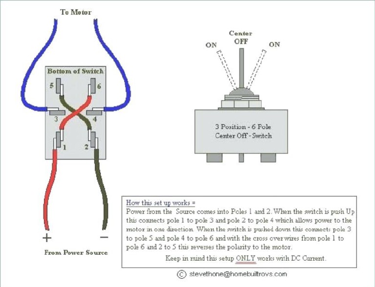
- Polarity and Grounding: For switches that handle polarized circuits or require grounding, the wiring diagram provides clear instructions on how to connect the wires correctly. This ensures proper circuit operation and safety.
By carefully following the wiring connections outlined in the diagram, electricians can ensure that the 3 Position Rotary Switch is integrated seamlessly into the circuit. This attention to detail minimizes the risk of electrical faults, ensures reliable operation, and promotes the longevity of the entire system.
Switch Type
In the context of a 3 Position Rotary Switch Wiring Diagram, understanding the switch type is crucial. It determines the switch’s behavior and how it interacts with the circuit. There are two primary switch types:
- Momentary Switch: A momentary switch only completes the circuit while the switch is physically held in the ON position. When released, the switch returns to its OFF position, breaking the circuit.
- Maintained Switch: A maintained switch remains in the ON or OFF position until it is physically switched again. It does not require continuous physical contact to maintain the circuit connection.
The wiring diagram will specify the type of switch used in the circuit. This information is critical because it affects how the switch is wired and the overall functionality of the circuit. For example, a momentary switch might be used to control a doorbell, where the circuit is only completed when the button is pressed. On the other hand, a maintained switch might be used to control a light fixture, where the switch remains in the ON position until it is switched off.
Understanding the switch type and its implications is essential for proper installation and troubleshooting of 3 Position Rotary Switches. By carefully analyzing the wiring diagram and selecting the appropriate switch type, electricians can ensure the reliable and efficient operation of electrical systems.
Panel Mounting
Within the context of a 3 Position Rotary Switch Wiring Diagram, panel mounting plays a crucial role in ensuring the switch’s secure and functional installation. It involves carefully considering the method used to mount the switch on a panel or enclosure to achieve a durable and reliable connection. Understanding the aspects of panel mounting empowers electricians to make informed decisions during the installation process.
- Mounting Hardware: The wiring diagram specifies the type and size of mounting hardware required to secure the switch to the panel. These components may include screws, nuts, or bolts, and their proper selection ensures a firm and stable installation.
- Panel Cutout: The diagram provides the dimensions and shape of the cutout required on the panel to accommodate the switch. This information guides the electrician in precisely cutting the panel, ensuring a snug fit and preventing any wobbling or movement of the switch.
- Mounting Orientation: The wiring diagram may specify the intended orientation of the switch on the panel. This is important for switches with specific functional markings or indicators that need to be visible and accessible to the user.
- Grounding Considerations: For switches that require grounding for safety or electrical noise reduction, the wiring diagram details the grounding method and the appropriate connection points on the switch. This information ensures proper grounding and minimizes the risk of electrical hazards.
By carefully considering the aspects of panel mounting outlined in the wiring diagram, electricians can ensure that the 3 Position Rotary Switch is securely and correctly installed. This attention to detail contributes to the overall reliability, safety, and functionality of the electrical system.
Terminal Arrangement
In the context of a 3 Position Rotary Switch Wiring Diagram, terminal arrangement holds critical importance. It serves as the blueprint for understanding the switch’s electrical connections and ensuring its proper installation and operation. By clearly defining the physical layout of the terminals on the switch, the terminal arrangement empowers electricians to confidently navigate the wiring process and achieve the desired circuit configuration.
The terminal arrangement is typically depicted on the wiring diagram as a schematic representation of the switch’s terminals. It illustrates the number, location, and orientation of each terminal, providing a clear visual guide for connecting wires. Additionally, the diagram may specify the type of terminals used, such as screw terminals, solder terminals, or quick-connect terminals.
Understanding the terminal arrangement is essential for several reasons. Firstly, it enables electricians to identify the correct terminals for each connection. This is crucial to ensure that the switch operates as intended and that the circuit functions safely. Secondly, the terminal arrangement guides the selection of appropriate wiring techniques. For example, if the switch uses screw terminals, the electrician will need to use the correct size and type of screwdriver to ensure a secure connection.
In practice, the terminal arrangement of a 3 Position Rotary Switch Wiring Diagram finds applications in diverse electrical systems. Electricians use this information to wire switches in lighting circuits, control circuits, and power distribution systems. By carefully following the terminal arrangement, they can ensure that the switch is properly integrated into the circuit and that the electrical system operates reliably and efficiently.
In summary, the terminal arrangement described in a 3 Position Rotary Switch Wiring Diagram is a critical component for understanding, installing, and maintaining electrical circuits. By providing a clear visual representation of the switch’s terminals, the terminal arrangement empowers electricians to make informed decisions about wiring connections, ensuring the safe and reliable operation of electrical systems.
Switch Function
In the realm of electrical engineering, 3 Position Rotary Switch Wiring Diagrams serve as essential guides for understanding, installing, and maintaining electrical circuits that incorporate these versatile switches. Among the crucial aspects depicted in these diagrams is the switch function, which elucidates the intended purpose of the switch within the circuit. Comprehending the switch function is paramount for electricians and engineers alike, as it provides insights into the switch’s role and behavior in the overall system.
- Circuit Control: Rotary switches are often employed to control the flow of electricity within a circuit. The switch function specifies the specific circuit elements that the switch controls, such as power sources, loads, or signal paths.
- Mode Selection: In circuits with multiple modes of operation, rotary switches are used to select the desired mode. The switch function describes the different modes available and how the switch transitions between them.
- Device Configuration: Some rotary switches are used to configure the operating parameters of electronic devices. The switch function explains how the switch settings affect device behavior, such as setting operating voltages, frequencies, or input/output options.
- Fault Isolation: Rotary switches can be incorporated into circuits as fault isolation devices. The switch function details how the switch is used to isolate faulty sections of the circuit, enabling easier troubleshooting and repair.
Understanding the switch function is crucial for properly installing and operating 3 Position Rotary Switches. By deciphering the intended purpose of the switch in the circuit, electricians can make informed decisions about switch selection, wiring connections, and circuit design. Moreover, a clear understanding of switch function facilitates effective troubleshooting and maintenance, ensuring the reliable and safe operation of electrical systems.


![[DIAGRAM] 3 Way Rotary Switch Wiring Diagram](https://i0.wp.com/mainetreasurechest.com/wp-content/uploads/2018/10/wfco-8955-wiring-diagram-inspirational-new-3-position-rotary-switch-wiring-diagram-of-wfco-8955-wiring-diagram-1.jpg?w=665&ssl=1)
Related Posts


