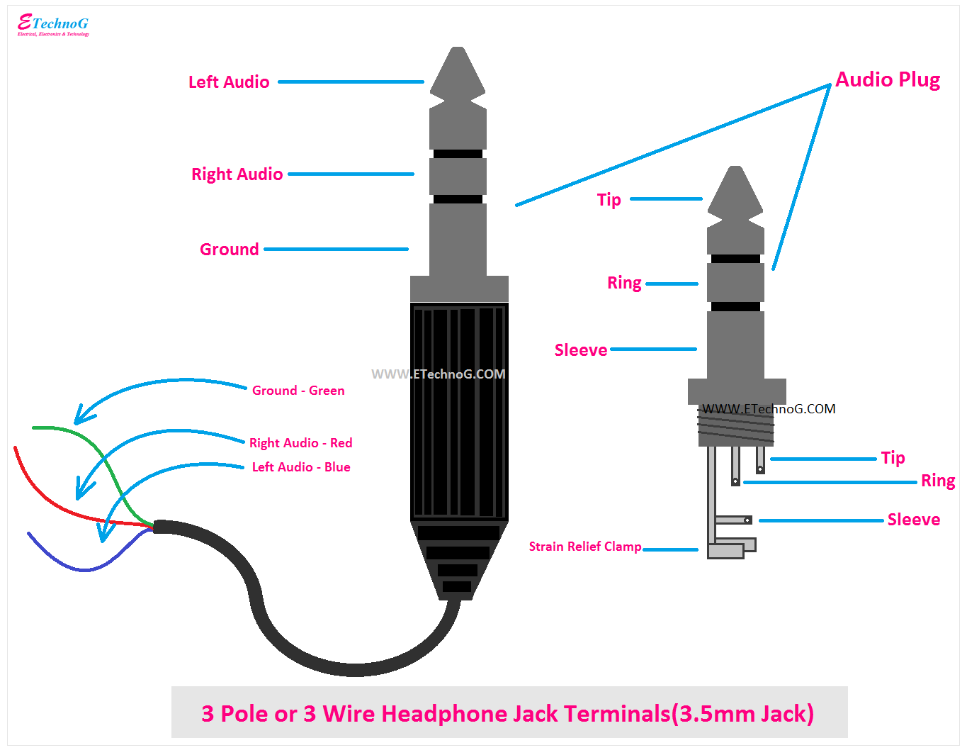
A 3 Pole 3.5 Mm Jack Wiring Diagram depicts the connections between the three poles (or terminals) of a 3.5 mm jack, specifying the purpose of each terminal and the corresponding wire colors. In audio applications, for instance, it might guide the wiring of a headset featuring a 3.5 mm jack, with three poles dedicated to left audio, right audio, and ground.
The diagram ensures proper signal transmission and compatibility between the jack and connected devices. It helps avoid misconnections, incorrect wiring, and potential damage to equipment. Moreover, standardization of wiring diagrams facilitates the design and production of electronic devices that utilize 3.5 mm jacks.
The introduction of the 3.5 mm jack in the late 1950s revolutionized audio connectivity. Its compact size and versatility made it the de facto standard for headphones, smartphones, and other portable devices. Today, the 3 Pole 3.5 Mm Jack Wiring Diagram remains an essential reference for manufacturers, audio engineers, and anyone working with these connections.
Understanding the key aspects of a 3 Pole 3.5 Mm Jack Wiring Diagram is crucial for designing and working with audio equipment. These aspects encompass various dimensions, impacting the functionality, compatibility, and performance of the jack.
- Terminal Count: Indicates the number of terminals (poles) in the jack, typically three.
- Jack Size: Specifies the physical size of the jack, measured in millimeters (mm), in this case, 3.5 mm.
- Contact Arrangement: Describes the specific layout and arrangement of the terminals within the jack.
- Wiring Scheme: Outlines the color-coded wires and their corresponding terminals.
- Signal Type: Indicates the type of signal transmitted through the jack, such as analog audio or digital data.
- Connector Type: Specifies the type of connector used to mate with the jack, such as TRS or TRRS.
- Compatibility: Highlights the devices and applications that are compatible with the jack based on its wiring and signal type.
- Industry Standards: Mentions relevant industry standards or specifications that govern the design and use of the jack.
- Applications: Lists various applications where the jack is commonly found, such as headphones, smartphones, and audio mixers.
- Troubleshooting: Provides guidance on identifying and resolving common issues related to the jack’s wiring and connections.
These aspects are interconnected and influence the overall functionality of the 3 Pole 3.5 Mm Jack Wiring Diagram. Understanding them enables proper installation, maintenance, and troubleshooting of audio systems that utilize this type of jack.
Terminal Count
The terminal count, referring to the number of terminals or poles in a 3 Pole 3.5 mm jack, is a crucial aspect that determines its functionality and compatibility. This aspect directly relates to the wiring diagram, as it specifies how many wires are needed and how they should be connected to transmit audio signals effectively.
- Number of Conductors: The terminal count corresponds to the number of conductors within the jack’s cable. A three-pole jack typically has three conductors: left audio, right audio, and ground.
- Signal Routing: The terminal count determines how audio signals are routed through the jack. A three-pole jack allows for the transmission of stereo audio signals, with separate left and right channels.
- Compatibility: The terminal count must match the corresponding device or cable to ensure proper signal transmission. Headphones with a three-pole jack will only work with devices that have compatible three-pole jacks.
- Additional Functions: Beyond basic audio transmission, some three-pole jacks may include additional terminals for functions such as microphone support or inline controls.
Understanding the terminal count is essential for designing and using 3 Pole 3.5 mm jacks. It ensures proper signal transmission, compatibility between devices, and support for advanced features when necessary. By considering the number of terminals and their arrangement, audio professionals and enthusiasts can optimize the performance and functionality of their audio systems.
Jack Size
The jack size, measured in millimeters (mm), directly influences the 3 Pole 3.5 Mm Jack Wiring Diagram. The physical dimensions of the jack determine the number and arrangement of terminals it can accommodate, impacting the wiring scheme and signal transmission capabilities.
In the case of a 3 Pole 3.5 mm jack, its compact size mandates a specific wiring arrangement to fit the three conductors (left audio, right audio, and ground) within the limited space. The 3.5 mm jack size has become a standard in portable audio devices due to its ability to transmit stereo audio signals while maintaining a small footprint.
Real-life examples of the relationship between jack size and wiring diagrams can be seen in various applications. Smartphones, laptops, and headphones commonly use 3.5 mm jacks, and their wiring diagrams must adhere to the physical constraints of the jack size. By understanding the jack size and its impact on the wiring diagram, manufacturers can design devices that are compatible with existing audio equipment and ensure optimal signal transmission.
This understanding has practical applications in troubleshooting audio issues. If a 3.5 mm jack is not properly wired or if the jack size does not match the corresponding device, audio signals may not be transmitted correctly. By referring to the 3 Pole 3.5 Mm Jack Wiring Diagram and considering the jack size, technicians can identify and resolve wiring problems, ensuring proper audio functionality.
In summary, the jack size plays a critical role in determining the 3 Pole 3.5 Mm Jack Wiring Diagram. The physical dimensions of the jack dictate the wiring arrangement and signal transmission capabilities. Understanding this relationship is essential for designing compatible audio devices, troubleshooting audio issues, and ensuring optimal audio performance.
Contact Arrangement
The contact arrangement within a 3 Pole 3.5 mm jack is a crucial aspect that directly influences the 3 Pole 3.5 Mm Jack Wiring Diagram. The specific layout and arrangement of the terminals determine how the wires are connected to transmit audio signals effectively and ensure proper functionality.
The contact arrangement dictates the position of each terminal (pole) within the jack. In a three-pole jack, the terminals are typically arranged in a triangular configuration, with each terminal dedicated to a specific signal: left audio, right audio, and ground. This arrangement ensures that the wires are connected to the correct terminals and that the audio signals are routed appropriately.
Understanding the contact arrangement is essential for designing compatible audio devices and troubleshooting audio issues. For instance, if the contact arrangement of a 3.5 mm jack does not match the wiring scheme of a device, audio signals may not be transmitted correctly or may result in distorted sound. By referring to the 3 Pole 3.5 Mm Jack Wiring Diagram and considering the contact arrangement, manufacturers and technicians can ensure proper connectivity and optimal audio performance.
In summary, the contact arrangement within a 3 Pole 3.5 mm jack is a fundamental aspect that directly influences the 3 Pole 3.5 Mm Jack Wiring Diagram. Understanding the specific layout and arrangement of the terminals is critical for designing compatible audio devices and resolving audio issues. It ensures proper signal transmission, minimizes potential problems, and contributes to the overall functionality of audio systems.
Wiring Scheme
Within the context of a 3 Pole 3.5 Mm Jack Wiring Diagram, the wiring scheme holds a prominent role in ensuring the proper flow of audio signals and maximizing the functionality of audio devices. It dictates the specific color-coding of wires and their corresponding connection to the jack’s terminals, providing a standardized framework for efficient and reliable audio signal transmission.
- Color-Coding: The wiring scheme assigns unique color-coding to each wire, typically red for right audio, white for left audio, and black or bare wire for ground. This color-coding simplifies the identification of wires during installation and maintenance, reducing the risk of incorrect connections and ensuring proper signal routing.
- Terminal Correspondence: The wiring scheme specifies the corresponding terminals on the jack where each color-coded wire should be connected. This ensures that the audio signals are directed to the appropriate channels (left, right, or ground), maintaining the integrity and quality of the transmitted audio.
- Compatibility: A standardized wiring scheme facilitates compatibility between different devices equipped with 3.5 mm jacks. By adhering to the established color-coding and terminal assignments, manufacturers can ensure that their devices can seamlessly connect and communicate with other compatible devices, regardless of their specific brands or models.
- Troubleshooting: The wiring scheme serves as a valuable reference guide for troubleshooting audio issues. If an audio connection is malfunctioning, referring to the wiring scheme can help identify incorrect wiring, loose connections, or other potential problems, enabling technicians and users to quickly resolve the issue and restore proper audio functionality.
In summary, the wiring scheme outlined in a 3 Pole 3.5 Mm Jack Wiring Diagram is a fundamental aspect that governs the efficient and standardized connection of audio devices. Its clear definition of color-coded wires and their corresponding terminals ensures proper signal transmission, compatibility between devices, and ease of troubleshooting, ultimately contributing to the optimal performance and reliability of audio systems.
Signal Type
Within the context of a 3 Pole 3.5 Mm Jack Wiring Diagram, the signal type holds paramount importance as it dictates the nature of the information being transmitted through the jack. Whether analog audio, digital data, or a combination thereof, the signal type profoundly influences the wiring scheme and the selection of appropriate components.
- Audio Signals: Analog audio signals, commonly found in audio applications, are continuous waveforms that represent sound. They require specific wiring and components to preserve their integrity during transmission.
- Digital Signals: Digital signals, prevalent in modern electronic devices, are discrete pulses that convey data. Their transmission through a 3.5 mm jack may involve additional protocols and circuitry.
- Hybrid Signals: Some applications utilize hybrid signals that combine analog and digital components. The wiring diagram must accommodate the unique requirements of each signal type.
- Compatibility Considerations: The signal type must align with the capabilities of the connected devices. Mismatched signal types can lead to signal degradation or device malfunctions.
Understanding the signal type and its implications is crucial for designing, troubleshooting, and maintaining audio systems that incorporate 3 Pole 3.5 mm jacks. By considering the signal characteristics, engineers can optimize the wiring scheme, select suitable components, and ensure seamless signal transmission.
Connector Type
Within the context of “3 Pole 3.5 Mm Jack Wiring Diagram,” the connector type plays a crucial role in determining the physical interface and signal compatibility between the jack and its mating connector. The connector type influences various aspects of the wiring diagram, including the number of conductors, contact arrangement, and overall functionality.
-
Tip, Ring, Sleeve (TRS):
A TRS connector features three conductors: tip, ring, and sleeve. It is commonly used for stereo audio applications, with the tip and ring carrying the left and right audio signals, respectively, and the sleeve serving as ground.
-
Tip, Ring, Ring, Sleeve (TRRS):
A TRRS connector has four conductors: tip, ring one, ring two, and sleeve. It is used in applications requiring additional functionality, such as inline microphones or remote controls. The extra ring conductor allows for the transmission of additional signals, such as microphone input or playback controls.
-
Compatibility:
The connector type must match between the jack and the mating connector to ensure proper signal transmission. Mismatched connectors can result in poor audio quality, intermittent connections, or even damage to the equipment.
-
Examples:
Examples of devices that commonly use 3.5 mm jacks with TRS or TRRS connectors include headphones, smartphones, laptops, and audio mixers.
Understanding the connector type is essential for designing and troubleshooting audio systems that incorporate 3 Pole 3.5 mm jacks. By considering the specific requirements of the application, such as the number of audio channels, the presence of a microphone, and the compatibility with existing devices, engineers can select the appropriate connector type and design a wiring diagram that ensures optimal performance.
Compatibility
Within the context of “3 Pole 3.5 Mm Jack Wiring Diagram,” the aspect of “Compatibility: Highlights the devices and applications that are compatible with the jack based on its wiring and signal type” holds great significance. It underscores the importance of understanding the jack’s specifications to ensure seamless connectivity and optimal performance.
-
Connector Compatibility:
The 3 Pole 3.5 mm jack must be compatible with the connector used to mate with it, typically TRS (Tip, Ring, Sleeve) or TRRS (Tip, Ring, Ring, Sleeve). Mismatched connectors can result in poor signal transmission or damage to the equipment.
-
Signal Type Compatibility:
The jack’s wiring and signal type must align with the devices it connects. For instance, a jack wired for analog audio signals will not be compatible with devices expecting digital signals.
-
Device Compatibility:
The jack’s compatibility extends to the devices it is used with. For example, a 3 Pole 3.5 mm jack with a microphone input is compatible with devices that support this functionality, such as headsets with built-in microphones.
-
Application Compatibility:
The jack’s compatibility also considers the specific applications it is intended for. For instance, a jack with a TRRS connector is suitable for applications requiring both audio and microphone signals, such as video conferencing.
Understanding the compatibility aspects of a 3 Pole 3.5 Mm Jack Wiring Diagram is crucial for ensuring proper signal transmission, avoiding device damage, and maximizing the functionality of audio systems. By considering these factors, engineers, technicians, and users can select the appropriate jack and wiring scheme for their specific applications, ensuring optimal performance and a seamless user experience.
Industry Standards
Within the context of “3 Pole 3.5 Mm Jack Wiring Diagram,” industry standards play a crucial role in ensuring uniformity, compatibility, and optimal performance of audio devices. These standards establish guidelines and specifications that manufacturers and engineers must adhere to when designing and producing 3.5 mm jacks.
-
IEC 61936:
The International Electrotechnical Commission (IEC) standard IEC 61936 specifies the dimensions, contact arrangement, and wiring scheme for 3.5 mm jacks. This standard ensures physical compatibility and proper signal transmission between jacks and connectors from different manufacturers.
-
ANSI/CTA-2030:
The American National Standards Institute (ANSI) and Consumer Technology Association (CTA) standard ANSI/CTA-2030 defines the color-coding scheme for wires used in 3.5 mm jacks. This standard ensures consistent identification of left and right audio channels, as well as ground, regardless of the manufacturer or application.
-
CTIA TRRS:
The Cellular Telecommunications Industry Association (CTIA) TRRS standard defines the pinout and functionality of 3.5 mm TRRS connectors, which include an additional contact for microphone input. This standard facilitates the use of headsets with built-in microphones, enabling hands-free communication in smartphones and other devices.
-
RoHS Compliance:
The Restriction of Hazardous Substances (RoHS) directive limits the use of certain hazardous substances in electrical and electronic equipment. Manufacturers must comply with RoHS regulations to ensure that 3.5 mm jacks are free from harmful materials, promoting environmental sustainability.
By adhering to these industry standards, manufacturers can guarantee that 3 Pole 3.5 mm Jack Wiring Diagrams are accurate, compatible, and meet the required performance criteria. These standards foster interoperability between devices, simplify troubleshooting, and enhance the overall user experience.
Applications
Within the realm of “3 Pole 3.5 Mm Jack Wiring Diagram,” the aspect of “Applications” holds great significance as it delves into the practical uses and real-world scenarios where this type of jack is employed. Understanding these applications provides a comprehensive view of the jack’s versatility and relevance in various electronic devices and systems.
-
Headphones and Earphones:
One of the most common applications of 3 Pole 3.5 mm jacks is in headphones and earphones. These audio devices utilize the jack for both audio signal transmission and, in some cases, microphone input, allowing users to listen to music, make phone calls, and communicate in online meetings.
-
Smartphones and Tablets:
Smartphones and tablets often incorporate 3 Pole 3.5 mm jacks to provide a convenient audio interface for headphones, external speakers, and other audio accessories. This enables users to enjoy music, videos, and other multimedia content while on the go.
-
Audio Mixers and Interfaces:
In the realm of professional audio, 3 Pole 3.5 mm jacks are commonly found on audio mixers and interfaces. These devices use the jacks to connect external audio sources, such as microphones, instruments, and playback devices, allowing for mixing, recording, and audio processing.
-
Portable Media Players:
Portable media players, including MP3 players and dedicated audio players, often feature 3 Pole 3.5 mm jacks for connecting headphones or external speakers. This allows users to enjoy their music libraries while on the move.
The diverse applications of 3 Pole 3.5 mm jacks highlight their versatility and widespread adoption in consumer electronics and professional audio equipment. Understanding these applications is essential for engineers, technicians, and users alike to fully grasp the role and significance of this jack type in the world of audio connectivity.
Troubleshooting
When working with 3 Pole 3.5 mm jacks, troubleshooting is a critical aspect that ensures proper functioning and optimal audio performance. The “Troubleshooting: Provides guidance on identifying and resolving common issues related to the jack’s wiring and connections.” section in a 3 Pole 3.5 Mm Jack Wiring Diagram serves as an invaluable resource for addressing and rectifying problems that may arise during installation, usage, or maintenance.
Common issues that this section addresses include loose or faulty connections, incorrect wiring, and compatibility problems. By providing step-by-step guidance and troubleshooting tips, it enables users to identify the root cause of the issue and apply appropriate solutions. This not only saves time and effort but also ensures the longevity and reliability of the jack and connected audio devices.
Real-life examples of troubleshooting scenarios within a 3 Pole 3.5 Mm Jack Wiring Diagram include resolving audio dropouts or intermittent sound, addressing noise or interference, and fixing compatibility issues between different devices. By referring to the troubleshooting section, users can systematically eliminate potential causes and implement effective remedies, ensuring seamless audio transmission and optimal listening experiences.


Related Posts


