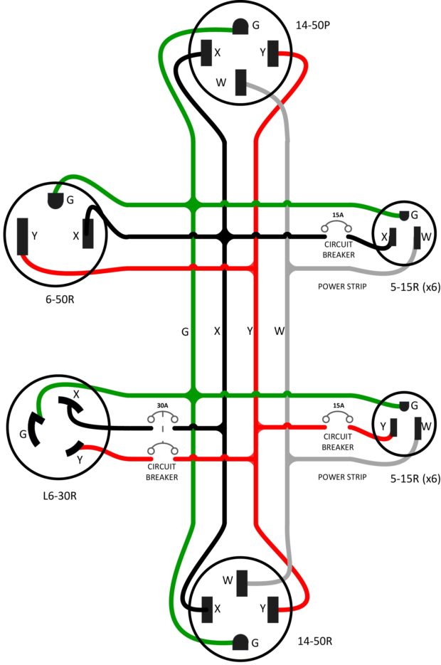
A 240v wiring diagram outlines the electrical connections for a 240-volt circuit. It provides a visual representation of the wiring components and their arrangement, including power sources, switches, outlets, and appliances. For instance, a 240v wiring diagram for an electric range illustrates the connections between the circuit breaker, wiring, and the range’s internal components.
These diagrams are crucial for electrical professionals and DIYers, ensuring the safe and efficient installation, maintenance, and troubleshooting of 240-volt circuits. Understanding 240v wiring diagrams helps prevent electrical hazards, such as short circuits and fires. A significant historical development was the introduction of alternating current (AC) systems, which made 240-volt circuits feasible and led to their wide adoption in residential and commercial applications.
In the following sections, we will delve into the intricacies of 240v wiring diagrams, exploring their components, safety considerations, and practical applications in various electrical systems.
Understanding the essential aspects of 240v wiring diagrams is crucial for safe and efficient electrical work. These diagrams provide a visual representation of the wiring components and their arrangement, which is vital for proper installation, maintenance, and troubleshooting.
- Components: Outlets, switches, wires, circuit breakers
- Connections: How components are linked together
- Circuit Protection: Devices like fuses and circuit breakers
- Voltage: 240 volts AC
- Current: Amperage flowing through the circuit
- Wiring Gauge: Thickness of the wires used
- Grounding: Path for electrical faults
- Safety Codes: Regulations for safe installation
- Troubleshooting: Identifying and resolving electrical issues
These aspects are interconnected and play vital roles in ensuring the proper functioning of 240v circuits. For instance, understanding the components and their connections helps identify potential hazards, while knowledge of circuit protection devices ensures safety in case of electrical faults. Furthermore, adhering to safety codes and understanding troubleshooting techniques enables safe maintenance and repair of electrical systems.
Components
Components such as outlets, switches, wires, and circuit breakers are fundamental elements in understanding 240v wiring diagrams. Each component plays a critical role in ensuring the safe and efficient operation of 240v circuits.
- Outlets: Outlets provide the connection point for appliances and devices to access the electrical current. In 240v wiring diagrams, outlets are typically rated for 20 amps and are designed to handle the higher voltage and amperage.
- Switches: Switches control the flow of electricity to outlets and lights. In 240v wiring diagrams, switches are rated for 20 amps or higher to handle the increased current.
- Wires: Wires carry the electrical current throughout the circuit. In 240v wiring diagrams, wires must be properly sized to handle the amperage and voltage of the circuit. Typically, 12-gauge or 10-gauge wires are used.
- Circuit breakers: Circuit breakers protect the circuit from overloads and short circuits. In 240v wiring diagrams, circuit breakers are typically rated for 20 amps or higher to provide adequate protection.
Understanding the components of a 240v wiring diagram is crucial for safe and effective electrical work. These components work together to deliver power to appliances and devices while ensuring protection against electrical hazards.
Connections
In the context of 240v wiring diagrams, connections play a pivotal role in ensuring the proper functioning and safety of the electrical system. These diagrams illustrate how the various components, such as outlets, switches, wires, and circuit breakers, are interconnected to create a functional circuit. Understanding these connections is critical for several reasons.
Firstly, correct connections are essential for the safe operation of the circuit. Improper connections can lead to electrical hazards, such as short circuits or fires. By understanding how the components are linked together, electricians can ensure that the circuit is wired correctly and meets safety codes. Secondly, understanding connections is crucial for troubleshooting electrical problems. When an issue arises, electricians can refer to the wiring diagram to identify the affected components and determine the most efficient repair strategy.
Real-life examples of connections in 240v wiring diagrams include the connection between the circuit breaker and the outlet. This connection allows the circuit breaker to protect the outlet from overloads and short circuits by cutting off the flow of electricity. Another example is the connection between the switch and the light fixture. This connection allows the switch to control the flow of electricity to the light fixture, turning it on or off.
In practical applications, understanding connections in 240v wiring diagrams is essential for various tasks, including:
- Installing new electrical outlets or circuits
- Troubleshooting and repairing electrical problems
- Expanding or modifying existing electrical systems
- Ensuring compliance with electrical codes and safety standards
By understanding the connections between components in 240v wiring diagrams, electricians and homeowners can ensure the safe and efficient operation of their electrical systems.
Circuit Protection
In the context of 240v wiring diagrams, circuit protection is of paramount importance. Circuit protection devices, such as fuses and circuit breakers, play a crucial role in ensuring the safety and proper operation of electrical circuits by protecting against overloads and short circuits. Understanding these devices is essential for electrical professionals and homeowners alike.
- Fuses: Fuses are one-time-use devices that interrupt the flow of electricity when the current exceeds a predetermined level. They consist of a thin wire that melts and breaks the circuit when excessive current flows. Fuses are often used in 240v circuits to protect against overloads and short circuits.
- Circuit breakers: Circuit breakers are reusable devices that automatically trip and cut off the flow of electricity when the current exceeds a safe level. They can be reset after the fault is corrected. Circuit breakers are commonly used in 240v circuits as they provide convenient and reliable protection against overloads and short circuits.
- Ground fault circuit interrupters (GFCIs): GFCIs are specialized circuit breakers that protect against electrical shocks by monitoring the balance of current between the hot and neutral wires. If an imbalance is detected, the GFCI quickly trips, interrupting the flow of electricity. GFCIs are often used in areas with high moisture levels, such as bathrooms and outdoor outlets.
- Arc fault circuit interrupters (AFCIs): AFCIs are circuit breakers that detect and interrupt electrical arcs, which can be a fire hazard. They are particularly important in areas where there is a high risk of electrical arcing, such as in older homes with knob-and-tube wiring.
These circuit protection devices work together to ensure the safety and reliability of 240v electrical circuits. By understanding their functions and applications, electricians and homeowners can make informed decisions about the selection and installation of appropriate circuit protection devices, mitigating the risk of electrical hazards and ensuring a safe electrical environment.
Voltage
In the realm of “240v Wiring Diagram”, the aspect of “Voltage: 240 volts AC” holds significant importance, influencing the design, components, and safety considerations of electrical systems. This section will delve into the multifaceted nature of “Voltage: 240 volts AC”, exploring its implications within the context of “240v Wiring Diagram”.
- Electrical Potential: 240 volts AC refers to the electrical potential difference between the two live wires in a 240v circuit. This potential difference provides the driving force for the flow of electrical current.
- Power Distribution: 240v circuits are commonly used for high-power appliances, such as electric stoves, clothes dryers, and air conditioners. The higher voltage allows for efficient power distribution, reducing the current required and minimizing energy losses.
- Safety Considerations: Working with 240 volts AC requires heightened safety precautions due to the increased risk of electrical shock and arc flash. Electricians must adhere to strict safety protocols and utilize appropriate personal protective equipment.
- Wiring Components: 240v wiring diagrams incorporate specific components rated for higher voltage, including 240v outlets, switches, and circuit breakers. These components are designed to withstand the higher voltage and amperage demands of 240v circuits.
Understanding the implications of “Voltage: 240 volts AC” is crucial for the safe and effective design, installation, and maintenance of 240v electrical systems. By considering the electrical potential, power distribution, safety concerns, and appropriate wiring components, electricians and homeowners can ensure the reliable and safe operation of 240v circuits.
Current
In the context of “240v Wiring Diagram”, understanding “Current: Amperage flowing through the circuit” is critical for ensuring the safe and efficient operation of electrical systems. Current, measured in amperes (amps), represents the rate of electron flow through a circuit and plays a significant role in determining the overall functionality and safety of a 240v wiring system.
The relationship between “Current: Amperage flowing through the circuit” and “240v Wiring Diagram” is bidirectional. On the one hand, the amperage flowing through a circuit directly impacts the design of the wiring diagram. Electrical components, such as wires, circuit breakers, and outlets, must be rated to handle the anticipated current load. Exceeding the current rating of any component can lead to overheating, electrical fires, or damage to equipment.
Conversely, the “240v Wiring Diagram” provides a roadmap for the safe and efficient flow of current through the circuit. It specifies the proper sizing and placement of components to minimize voltage drop, reduce power loss, and ensure the reliable delivery of electricity to appliances and devices. By adhering to the wiring diagram, electricians can ensure that the circuit can safely handle the intended current load.
Real-life examples of “Current: Amperage flowing through the circuit” within “240v Wiring Diagram” include:
- Electric stoves: Electric stoves typically operate on 240 volts and draw high currents, often exceeding 30 amps. The wiring diagram must account for this high current demand by specifying appropriately sized wires and circuit breakers.
- Air conditioners: Air conditioners also operate on 240 volts and can draw significant currents, especially during startup. The wiring diagram must ensure that the circuit can handle the high inrush current without tripping the circuit breaker.
- Lighting circuits: Lighting circuits typically operate at lower currents, but the wiring diagram must still consider the total current draw of all the lights on the circuit to ensure that the wires and circuit breaker are appropriately sized.
Understanding the connection between “Current: Amperage flowing through the circuit” and “240v Wiring Diagram” is essential for electrical professionals and homeowners alike. By considering the current load, electricians can design and install safe and efficient 240v wiring systems, and homeowners can make informed decisions about the electrical demands of their appliances and devices.
Wiring Gauge
In the realm of “240v Wiring Diagram”, the aspect of “Wiring Gauge: Thickness of the wires used” holds significant importance, influencing the safety, efficiency, and overall functionality of electrical systems. This section will delve into the multifaceted nature of “Wiring Gauge: Thickness of the wires used”, exploring its implications within the context of “240v Wiring Diagram”.
- Current Capacity: The thickness of wires, measured in gauge, directly affects their current-carrying capacity. Thicker wires, with lower gauge numbers, can handle higher currents without overheating.
- Voltage Drop: Thicker wires also experience less voltage drop over longer distances, ensuring that appliances and devices receive the intended voltage. This is particularly important in 240v circuits, where voltage drop can be more pronounced.
- Safety: Using wires with the appropriate gauge is crucial for safety. Undersized wires can overheat and pose a fire hazard, while oversized wires may not provide adequate protection against short circuits.
- Code Compliance: Electrical codes specify the minimum wire gauge that can be used for different applications. Adhering to these codes ensures compliance with safety standards and prevents potential hazards.
Understanding the implications of “Wiring Gauge: Thickness of the wires used” is essential for the safe and efficient design, installation, and maintenance of 240v electrical systems. By considering the current capacity, voltage drop, safety concerns, and code compliance, electricians and homeowners can make informed decisions about the appropriate wire gauge for their electrical needs, ensuring the reliable and safe operation of 240v circuits.
Grounding
In the context of “240v Wiring Diagram”, “Grounding: Path for electrical faults” plays a critical role in ensuring the safety and proper functioning of electrical systems. Grounding provides a deliberate path for electrical faults to follow, preventing them from taking unintended paths that could pose a hazard to people or property.
Grounding is achieved by connecting all exposed metal parts of an electrical system to the ground. This connection creates a low-resistance path for any stray electrical current to flow back to the electrical panel and into the earth. Without proper grounding, electrical faults can cause shocks, fires, or damage to equipment.
In 240v wiring diagrams, grounding is typically represented by a green or bare copper wire that runs alongside the circuit wires. This grounding wire is connected to the ground bus in the electrical panel and to all metal enclosures, such as outlet boxes and switch boxes. By providing a dedicated path for electrical faults, grounding helps to ensure that any excess current is safely discharged into the ground, preventing it from flowing through people or causing damage.
Real-life examples of “Grounding: Path for electrical faults” within “240v Wiring Diagram” include:
- The grounding wire in an electrical outlet provides a path for any stray current to flow back to the electrical panel, preventing it from shocking a person who touches the outlet.
- The grounding wire in a light fixture prevents electrical faults from causing the fixture to become energized, which could pose a fire hazard.
- The grounding wire in an electric range provides a path for any stray current to flow back to the electrical panel, preventing it from causing a shock to the person using the range.
Understanding the connection between “Grounding: Path for electrical faults” and “240v Wiring Diagram” is essential for the safe design, installation, and maintenance of electrical systems. By ensuring proper grounding, electricians and homeowners can help to prevent electrical hazards and ensure the reliable operation of 240v electrical systems.
Safety Codes
In the realm of “240v Wiring Diagram”, “Safety Codes: Regulations for safe installation” stand as a cornerstone, ensuring the safe design, installation, and maintenance of electrical systems. These codes provide a comprehensive set of rules and guidelines that govern every aspect of electrical work, from the selection of materials to the testing and inspection of completed installations.
The connection between “Safety Codes: Regulations for safe installation” and “240v Wiring Diagram” is inseparable. Safety codes form the foundation upon which 240v wiring diagrams are built. By adhering to these codes, electricians can ensure that 240v circuits are installed in a manner that minimizes the risk of electrical hazards, such as shocks, fires, and explosions.
Real-life examples of “Safety Codes: Regulations for safe installation” within “240v Wiring Diagram” include:
- The National Electrical Code (NEC) specifies the minimum wire size that can be used for 240v circuits, ensuring that wires can safely handle the current load without overheating.
- The NEC also requires that all 240v circuits be protected by a circuit breaker or fuse, which will trip if the current exceeds a safe level, preventing damage to equipment or electrical fires.
- Local building codes may have additional requirements for 240v installations, such as the use of arc-fault circuit interrupters (AFCIs), which can help to prevent electrical fires caused by arcing faults.
Understanding the connection between “Safety Codes: Regulations for safe installation” and “240v Wiring Diagram” is essential for the safe design, installation, and maintenance of electrical systems. By adhering to safety codes, electricians and homeowners can help to prevent electrical hazards and ensure the reliable operation of 240v circuits.
Troubleshooting
In the context of “240v Wiring Diagram”, “Troubleshooting: Identifying and resolving electrical issues” plays a critical role in ensuring the safe and reliable operation of electrical systems. Troubleshooting involves identifying and resolving electrical faults to restore proper functioning and prevent potential hazards.
Troubleshooting is a crucial component of 240v wiring diagrams as it provides a systematic approach to diagnosing and resolving electrical problems. By understanding the relationship between components and circuits depicted in the wiring diagram, electricians can efficiently identify potential issues and implement appropriate solutions.
Real-life examples of “Troubleshooting: Identifying and resolving electrical issues” within “240v Wiring Diagram” include:
- Troubleshooting a faulty outlet by checking for loose connections, damaged wiring, or tripped circuit breakers.
- Identifying a short circuit by examining the wiring diagram to locate the affected circuit and isolating the fault.
- Diagnosing a malfunctioning appliance by referring to the wiring diagram to trace the electrical connections and identify potential issues.
Understanding the practical applications of troubleshooting within 240v wiring diagrams empowers electricians and homeowners to safely and effectively maintain electrical systems. By utilizing wiring diagrams for troubleshooting, they can minimize downtime, prevent electrical hazards, and ensure the longevity of electrical equipment.
In conclusion, “Troubleshooting: Identifying and resolving electrical issues” is an integral part of “240v Wiring Diagram”, providing a valuable tool for diagnosing and resolving electrical problems. By understanding the connection between these two aspects, electricians can effectively maintain and repair electrical systems, ensuring safety and reliability.


Related Posts


