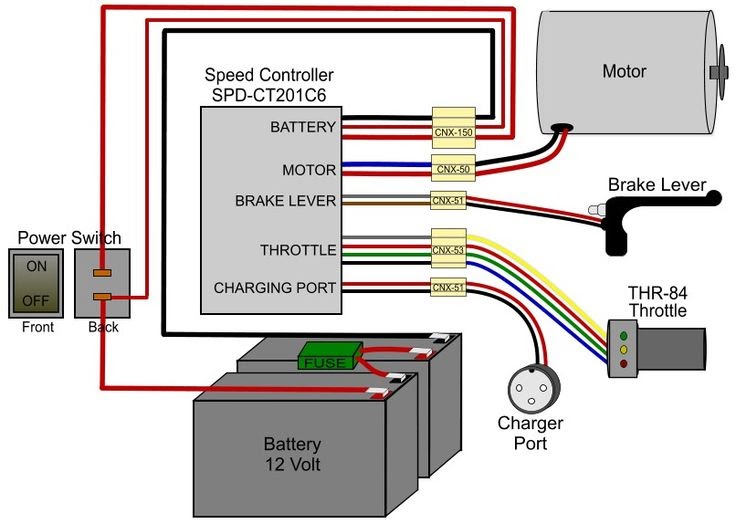
A 24 Volt Electric Scooter Wiring Diagram outlines the electrical connections of a 24-volt electric scooter. It visually represents how the various electrical components, such as the motor, battery, controller, and throttle, are connected to each other and to the power source. For example, a typical 24-volt electric scooter wiring diagram might show the battery connected to the controller, which is then connected to the motor. The throttle would be connected to the controller, allowing the rider to control the speed of the scooter.
Wiring diagrams are essential for understanding the electrical system of a 24-volt electric scooter and for troubleshooting any electrical problems. They can also be used to modify or upgrade the electrical system. One key historical development in the field of electric scooter wiring diagrams is the advent of computer-aided design (CAD) software, which has made it much easier to create and modify wiring diagrams.
This article will provide an in-depth overview of 24 Volt Electric Scooter Wiring Diagrams, including their components, benefits, and how to read and interpret them. We will also discuss some common troubleshooting tips and provide resources for finding wiring diagrams for specific electric scooter models.
A 24 Volt Electric Scooter Wiring Diagram is a blueprint of the electrical system of a 24-volt electric scooter. It visually represents how the various electrical components, such as the motor, battery, controller, and throttle, are connected to each other and to the power source. Wiring diagrams are essential for understanding the electrical system of an electric scooter and for troubleshooting any electrical problems. They can also be used to modify or upgrade the electrical system.
- Components: Battery, motor, controller, throttle, wiring harness
- Connections: How the components are connected to each other
- Layout: The physical arrangement of the components
- Symbols: The graphical symbols used to represent the components
- Color coding: The use of different colors to identify different types of wires
- Troubleshooting: Using the wiring diagram to identify and fix electrical problems
- Modification: Using the wiring diagram to make changes to the electrical system
- Upgrading: Using the wiring diagram to upgrade the electrical system with new or improved components
- Safety: The importance of following the wiring diagram to ensure the electrical system is safe
- Maintenance: Using the wiring diagram to perform routine maintenance on the electrical system
These key aspects of a 24 Volt Electric Scooter Wiring Diagram provide a comprehensive understanding of the electrical system of an electric scooter. By understanding these aspects, you can troubleshoot and fix electrical problems, modify or upgrade the electrical system, and ensure the safe and proper operation of your electric scooter.
Components
The components of a 24 Volt Electric Scooter Wiring Diagram are the battery, motor, controller, throttle, and wiring harness. These components work together to provide power to the electric scooter and allow the rider to control its speed and direction. Each component plays a vital role in the operation of the electric scooter, and a thorough understanding of their functions is essential for troubleshooting and repairing any electrical problems.
- Battery: The battery provides the electrical power to the electric scooter. It is typically a rechargeable lithium-ion battery, which is lightweight and provides a long range. The battery capacity is measured in amp-hours (Ah), which indicates how long the battery can power the scooter on a single charge.
- Motor: The motor converts the electrical energy from the battery into mechanical energy, which drives the wheels of the electric scooter. The motor is typically a brushless DC motor, which is efficient and provides smooth acceleration.
- Controller: The controller regulates the flow of electricity from the battery to the motor. It also controls the speed and direction of the electric scooter. The controller is typically a small electronic device that is mounted on the frame of the electric scooter.
- Throttle: The throttle is a handlebar-mounted control that allows the rider to control the speed of the electric scooter. When the rider twists the throttle, it sends a signal to the controller, which increases the power to the motor and accelerates the scooter. When the rider releases the throttle, the power to the motor is reduced and the scooter slows down.
- Wiring harness: The wiring harness is a bundle of wires that connects the battery, motor, controller, and throttle. It provides the electrical pathways for the flow of electricity between the components. The wiring harness is typically made of flexible, insulated wire, and it is routed through the frame of the electric scooter to protect it from damage.
These components are essential for the proper operation of a 24 Volt Electric Scooter Wiring Diagram. By understanding the role of each component, you can troubleshoot and repair any electrical problems that may arise. You can also upgrade or modify the electrical system to improve the performance of your electric scooter.
Connections
In a 24 Volt Electric Scooter Wiring Diagram, connections refer to the electrical pathways that allow the various components of the scooter to communicate and function as a cohesive system. Understanding these connections is crucial for troubleshooting electrical issues, customizing the scooter, or upgrading its performance. Here are several key aspects to consider:
- Battery to Controller: The battery is the power source for the electric scooter, and its connection to the controller is vital. This connection typically involves thick wires to handle the high current draw of the motor. Proper connections ensure the controller receives a stable voltage supply to regulate the scooter’s speed and performance.
- Controller to Motor: The controller acts as the brain of the scooter, managing the flow of electricity to the motor. The connection between the controller and the motor is critical for controlling the scooter’s speed and torque. This connection often utilizes heavy-duty wires to accommodate the high currents involved in motor operation.
- Throttle to Controller: The throttle is the rider’s interface for controlling the scooter’s speed. When the throttle is twisted, it sends a signal to the controller, which adjusts the power output to the motor. This connection typically involves a combination of wires and connectors to ensure a responsive and reliable throttle response.
- Wiring Harness: The wiring harness is a bundle of wires that connects all the electrical components of the scooter. It provides a structured and organized way to route the wires, protecting them from damage and ensuring a clean and efficient electrical system. The wiring harness is designed to handle the specific voltage and current requirements of the scooter.
These connections are essential for the proper operation of a 24 Volt Electric Scooter Wiring Diagram. By understanding the role and implications of each connection, you can maintain, troubleshoot, and enhance your electric scooter’s electrical system effectively.
Layout
In the context of a 24 Volt Electric Scooter Wiring Diagram, the physical arrangement of the components plays a crucial role in ensuring optimal performance, safety, and ease of maintenance. It encompasses the placement, orientation, and spacing of electrical components, affecting factors such as heat dissipation, accessibility, and overall functionality of the system.
- Component Placement: The strategic positioning of components, such as the battery, controller, and motor, is crucial for weight distribution, heat management, and protection from external elements. Careful placement optimizes the center of gravity, minimizes heat buildup, and enhances the scooter’s stability and handling.
- Wire Routing: The organization and routing of wires throughout the scooter’s frame impact safety and reliability. Proper wire management prevents tangles, reduces the risk of shorts or damage, and facilitates maintenance. Strategic placement of wires ensures minimal interference with other components, enhancing the overall efficiency and longevity of the system.
- Component Accessibility: The physical arrangement should consider the accessibility of components for maintenance and repairs. Easy access to the battery, controller, and other critical parts simplifies troubleshooting, routine maintenance, and potential upgrades or replacements, extending the scooter’s lifespan and ensuring peak performance.
- Heat Dissipation: The layout should promote efficient heat dissipation to prevent overheating and potential damage to components. Adequate spacing around heat-generating components, such as the motor and controller, allows for proper airflow and cooling. This consideration enhances the system’s reliability and durability, ensuring prolonged operation without compromising performance.
By carefully considering the physical arrangement of components in a 24 Volt Electric Scooter Wiring Diagram, manufacturers and users can optimize the scooter’s functionality, safety, and ease of maintenance. A well-planned layout contributes to a reliable, efficient, and enjoyable riding experience.
Symbols
In the context of a 24 Volt Electric Scooter Wiring Diagram, symbols play a vital role in representing various electrical components and their interconnections. These graphical symbols provide a standardized visual language that simplifies the understanding, analysis, and troubleshooting of the electrical system. The use of symbols allows for clear and concise representation, enabling technicians and users to quickly identify and locate components, even in complex wiring diagrams.
The symbols employed in a 24 Volt Electric Scooter Wiring Diagram are established according to industry standards and conventions. Each symbol represents a specific component, such as a battery, motor, controller, or switch. The shape, size, and orientation of these symbols convey information about the component’s function and its connection to other elements in the circuit. By adhering to these standards, wiring diagrams become universally understandable, facilitating communication and collaboration among professionals and enthusiasts.
Practical applications of understanding the symbols used in a 24 Volt Electric Scooter Wiring Diagram are numerous. For instance, when troubleshooting an electrical issue, technicians can use the diagram to identify the location of a faulty component based on its symbol. Additionally, when modifying or upgrading the scooter’s electrical system, the symbols allow users to determine the appropriate connections and avoid potential errors. Furthermore, the symbols serve as a valuable educational tool, helping users comprehend the functionality and interrelationships of the various electrical components in the scooter.
In summary, the symbols used in a 24 Volt Electric Scooter Wiring Diagram provide a critical visual representation of the electrical system’s components and their connections. These symbols adhere to standardized conventions, enabling clear communication and understanding. Practical applications of this knowledge include troubleshooting, system modifications, and educational purposes. By leveraging the power of visual symbols, wiring diagrams become powerful tools for maintaining, repairing, and enhancing the electrical performance of electric scooters.
Color coding
In the context of a 24 Volt Electric Scooter Wiring Diagram, color coding plays a crucial role in simplifying the identification and tracing of different types of wires. By assigning specific colors to different wire functions or purposes, technicians and users can quickly distinguish between them, reducing the risk of errors during installation, maintenance, or troubleshooting.
The use of color coding in 24 Volt Electric Scooter Wiring Diagrams is not merely a cosmetic choice but a critical component for ensuring the proper functioning and safety of the electrical system. Each color represents a specific type of wire, such as positive, negative, ground, or signal wires. By adhering to standardized color codes, manufacturers and technicians can ensure consistency across different scooter models and simplify the process of identifying and connecting wires correctly.
Real-life examples of color coding in 24 Volt Electric Scooter Wiring Diagrams include:
- Red wires typically represent positive (+) connections, indicating the flow of current from the battery to various electrical components.
- Black wires are commonly used for negative (-) connections, completing the electrical circuit and allowing current to return to the battery.
- Green or yellow wires with green stripes are often used for ground connections, providing a reference point for electrical circuits and ensuring safety by directing stray currents away from sensitive components.
- Blue or white wires may be used for signal wires, carrying data or control signals between different components, such as the throttle and the controller.
Understanding the color coding system used in 24 Volt Electric Scooter Wiring Diagrams is essential for practical applications such as:
- Troubleshooting electrical issues: By identifying the color code of a faulty wire, technicians can quickly trace its origin and determine the cause of the problem.
- Modifying or upgrading the electrical system: Color coding allows users to easily identify the correct wires to connect when adding new components or upgrading existing ones.
- Ensuring safety: Correctly following the color coding scheme helps prevent accidental short circuits or damage to electrical components due to improper connections.
In summary, color coding in 24 Volt Electric Scooter Wiring Diagrams is a critical element that enhances the clarity, accuracy, and safety of the electrical system. By assigning specific colors to different wire functions, technicians and users can quickly identify, connect, and troubleshoot wires, ensuring the optimal performance and longevity of the electric scooter.
Troubleshooting
In the context of “24 Volt Electric Scooter Wiring Diagram”, troubleshooting holds immense significance. By utilizing the wiring diagram as a roadmap, technicians and users can effectively identify and resolve electrical issues, ensuring the smooth operation and longevity of the electric scooter.
- Identifying Faulty Components: The wiring diagram serves as a comprehensive guide to trace the flow of electricity throughout the scooter. By analyzing the diagram, technicians can pinpoint the exact component causing the electrical problem, whether it’s a faulty battery, a loose connection, or a damaged wire.
- Real-Life Examples: Electrical problems in 24 Volt Electric Scooters can manifest in various ways. For instance, a loose connection in the wiring harness may cause intermittent power loss or flickering lights. By referring to the wiring diagram, technicians can quickly identify the affected circuit and locate the point of failure.
- Implications for Safety: Troubleshooting electrical problems using the wiring diagram is not only about restoring functionality but also about ensuring the safety of the rider. Electrical faults can lead to overheating, short circuits, or even fires if left unattended. By promptly identifying and fixing electrical issues, users can prevent potential hazards and ride with peace of mind.
- DIY Repairs and Maintenance: Armed with the wiring diagram, skilled individuals can attempt DIY repairs and maintenance on their electric scooters. By understanding the electrical connections and component locations, they can troubleshoot and fix minor electrical problems without relying solely on professional assistance.
In conclusion, the ability to troubleshoot electrical problems using the wiring diagram empowers users to maintain the optimal performance and safety of their 24 Volt Electric Scooters. By leveraging the wiring diagram as a diagnostic tool, they can identify and resolve electrical issues, preventing minor inconveniences from escalating into major breakdowns. Furthermore, the knowledge gained from troubleshooting enhances the overall understanding of the electric scooter’s electrical system, fostering a sense of ownership and self-reliance among users.
Modification
Within the context of “24 Volt Electric Scooter Wiring Diagram”, the aspect of “Modification: Using the wiring diagram to make changes to the electrical system” takes on significant importance. It empowers users to customize their electric scooters and enhance their performance, safety, or aesthetics. This comprehensive guide will delve into the various facets of modification, exploring its potential, real-life examples, and implications.
- Upgrading Components: The wiring diagram provides a roadmap for upgrading electrical components, such as the motor, battery, or controller. Users can identify compatible components and understand their electrical requirements to optimize the scooter’s speed, range, or power.
- Adding Accessories: The wiring diagram serves as a guide for integrating additional accessories, such as lights, horns, or GPS devices. It helps users determine the appropriate wiring connections and ensure the accessories are compatible with the scooter’s electrical system.
- Customizing Lighting: Modifications to the wiring diagram can enable the customization of lighting systems. Users can add additional lights, change the color or intensity of existing lights, or implement unique lighting patterns to enhance visibility or personal style.
- Troubleshooting and Repair: The wiring diagram is a valuable tool for troubleshooting and repairing electrical issues. By tracing the electrical connections and identifying potential failure points, users can effectively diagnose and fix problems, extending the lifespan of their electric scooters.
In conclusion, the ability to modify the electrical system of a 24 Volt Electric Scooter using the wiring diagram unlocks a world of possibilities for customization, performance enhancement, and problem-solving. By understanding the electrical connections and component locations, users can tailor their electric scooters to meet their specific needs and preferences, achieving a truly personalized and optimized riding experience.
Upgrading
Within the realm of “24 Volt Electric Scooter Wiring Diagram,” the topic of “Upgrading: Using the wiring diagram to upgrade the electrical system with new or improved components” holds immense significance. It empowers users to enhance the performance, efficiency, and overall riding experience of their electric scooters. By leveraging the wiring diagram as a guide, users can navigate the electrical system and make informed decisions about component upgrades, ensuring compatibility and optimal functioning.
- Motor Upgrade: Replacing the stock motor with a higher-powered one can significantly boost the scooter’s speed and acceleration capabilities, making it more suitable for hilly terrain or heavier riders. The wiring diagram provides insights into the motor’s electrical requirements, ensuring a seamless integration into the existing system.
- Battery Upgrade: Upgrading to a higher-capacity battery extends the scooter’s range, allowing for longer rides without the worry of running out of power. The wiring diagram helps determine the compatibility of different batteries and their charging specifications, ensuring safe and efficient operation.
- Controller Upgrade: A performance controller can optimize the communication between the battery, motor, and throttle, resulting in smoother acceleration, improved torque, and enhanced overall responsiveness. The wiring diagram guides the user in selecting the appropriate controller and integrating it into the electrical system.
- Accessory Integration: The wiring diagram serves as a roadmap for incorporating additional accessories, such as lights, GPS devices, or phone chargers. It helps users identify the correct wiring connections and ensures the accessories are compatible with the scooter’s electrical system, preventing potential overloading or damage.
In conclusion, the ability to upgrade the electrical system of a 24 Volt Electric Scooter using the wiring diagram empowers users to tailor their scooters to meet their specific needs and preferences. By understanding the electrical connections and component locations, users can unlock new levels of performance, range, and functionality, transforming their electric scooters into truly personalized and optimized riding machines.
Safety
In the context of “24 Volt Electric Scooter Wiring Diagram,” the aspect of “Safety: The importance of following the wiring diagram to ensure the electrical system is safe” takes paramount importance. Understanding and adhering to the wiring diagram is not merely a matter of functionality but a critical component of ensuring the safety of the user and the scooter itself. The wiring diagram serves as a roadmap for the electrical system, providing detailed information about the connections, components, and their proper configuration.
The consequences of neglecting the wiring diagram can be severe. Incorrect wiring or connections can lead to electrical faults, malfunctions, and even potential hazards such as overheating, short circuits, or fires. By following the wiring diagram meticulously, users can ensure that the electrical system operates as intended, minimizing the risk of accidents or damage.
Real-life examples of the importance of following the wiring diagram abound. For instance, a loose connection in the wiring harness can cause intermittent power loss or flickering lights. If left unattended, this seemingly minor issue could escalate into a more serious problem, potentially leading to a complete electrical failure. By referring to the wiring diagram, users can quickly identify and rectify the loose connection, preventing further complications.
The practical applications of understanding the wiring diagram extend beyond troubleshooting. It empowers users to perform maintenance and upgrades on their electric scooters with confidence. By referencing the wiring diagram, they can identify the correct wires to connect when adding new components or modifying the electrical system. This knowledge helps prevent accidental damage, ensures compatibility, and maintains the overall safety and integrity of the scooter.
In conclusion, the importance of following the wiring diagram to ensure the electrical system is safe cannot be overstated. The wiring diagram provides a comprehensive guide to the electrical connections and components, enabling users to maintain, troubleshoot, and modify their electric scooters safely and effectively. By adhering to the wiring diagram, users can minimize electrical hazards, prevent accidents, and extend the lifespan of their scooters.
Maintenance
Within the context of “24 Volt Electric Scooter Wiring Diagram,” the aspect of “Maintenance: Using the wiring diagram to perform routine maintenance on the electrical system” holds significant importance. Regular maintenance is crucial for ensuring the optimal performance, safety, and longevity of an electric scooter. The wiring diagram serves as an indispensable tool in performing routine maintenance tasks, enabling users to identify, inspect, and maintain the electrical components of their scooters effectively.
- Component Inspection: The wiring diagram provides a comprehensive overview of the electrical system, allowing users to locate and visually inspect individual components such as wires, connectors, and terminals. This inspection helps identify any signs of damage, corrosion, or loose connections, enabling timely repairs or replacements.
- Electrical Testing: The wiring diagram guides users in performing electrical tests to assess the functionality of various components. Using a multimeter, users can measure voltage, continuity, and resistance to identify potential issues. Early detection of electrical faults through routine testing prevents minor problems from escalating into major breakdowns.
- Connector Maintenance: Connectors play a vital role in ensuring reliable electrical connections. The wiring diagram helps users locate and inspect connectors, ensuring they are clean, free of corrosion, and properly secured. Regular maintenance of connectors prevents intermittent electrical issues and ensures optimal current flow throughout the system.
- Battery Maintenance: The battery is the heart of an electric scooter’s electrical system. The wiring diagram provides insights into the battery’s connections and charging specifications. Regular monitoring of the battery’s voltage, electrolyte levels, and overall condition helps maintain its performance and extends its lifespan.
By leveraging the wiring diagram for routine maintenance, users can proactively identify and address potential electrical issues, minimizing the risk of unexpected breakdowns and ensuring the safety and reliability of their electric scooters. Regular maintenance not only extends the lifespan of the scooter but also enhances the riding experience, giving users peace of mind and confidence on the road.


Related Posts


