A 230v 3 Phase Motor Wiring Diagram provides a visual representation of how to connect the terminals of a 3-phase motor to a 230-volt, 3-phase power source. This diagram ensures that the motor is wired correctly, allowing it to operate efficiently and safely.
Proper wiring of a 3-phase motor is crucial to avoid damage to the motor and ensure its optimal performance. The diagram specifies the connections between the motor’s terminals and the power source’s phases, ensuring that the motor receives the correct voltage and current to rotate.
In industrial settings, 230v 3 Phase Motor Wiring Diagrams play a vital role in the operation of various machinery and equipment. They enable the safe and efficient use of these motors, ensuring that they can perform their intended tasks effectively.
230v 3 Phase Motor Wiring Diagrams are crucial for the safe and efficient operation of 3-phase motors in various industrial applications. Understanding the essential aspects of these diagrams is key to ensuring proper installation and maintenance of the motors.
- Electrical Safety: Wiring diagrams provide guidance on proper connections to prevent electrical hazards, ensuring the safety of personnel and equipment.
- Motor Performance: Correct wiring ensures that the motor receives the correct voltage and current to operate at its optimal efficiency and performance.
- Motor Protection: Wiring diagrams specify the appropriate overcurrent protection devices to safeguard the motor from damage in the event of overloads or short circuits.
- Maintenance and Troubleshooting: Diagrams assist in troubleshooting and maintenance tasks by providing a clear visual representation of the motor’s electrical connections.
- Compliance with Regulations: Adhering to wiring diagrams helps ensure compliance with electrical codes and standards, ensuring safety and reliability.
- Motor Control: Wiring diagrams provide information on motor control methods, such as forward/reverse rotation, speed control, and braking.
- Power Factor Correction: Diagrams may include guidance on power factor correction techniques to improve the efficiency of the motor system.
- Grounding: Diagrams specify the proper grounding connections to ensure the safety of personnel and the protection of the motor from electrical faults.
These aspects highlight the importance of 230v 3 Phase Motor Wiring Diagrams in ensuring the safe, efficient, and reliable operation of motors in industrial settings. Proper understanding and application of these diagrams are essential for the effective utilization of electrical systems.
Electrical Safety
In the context of 230v 3 Phase Motor Wiring Diagrams, electrical safety is paramount. These diagrams provide detailed instructions on how to correctly connect the motor to a power source, ensuring that all electrical connections are secure and meet safety standards. By adhering to these diagrams, electrical hazards such as short circuits, overloads, and ground faults can be prevented, safeguarding both personnel and equipment from harm.
- Proper Grounding: Wiring diagrams specify the proper grounding connections for the motor. Grounding provides a low-resistance path for fault currents to flow, preventing them from passing through equipment or personnel, reducing the risk of electrical shock and equipment damage.
- Overcurrent Protection: Diagrams indicate the appropriate overcurrent protection devices, such as fuses or circuit breakers, to be used with the motor. These devices protect the motor from damage caused by excessive current flow, preventing overheating, insulation failure, and potential fire hazards.
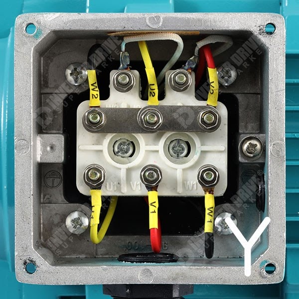
- Terminals and Connections: Wiring diagrams clearly illustrate the terminals on the motor and the corresponding connections to the power source. Proper identification and secure connections are crucial to prevent loose connections, arcing, and potential electrical fires.
- Wire Sizing and Protection: Diagrams specify the appropriate wire sizes and types to be used for connecting the motor to the power source. Correct wire sizing ensures that the wires can safely carry the required current without overheating or insulation breakdown, preventing electrical hazards.
By following the guidance provided in 230v 3 Phase Motor Wiring Diagrams, electrical contractors and maintenance personnel can ensure that motors are connected safely and efficiently. This not only protects personnel and equipment but also ensures the reliable and trouble-free operation of electrical systems.
Motor Performance
In the context of 230v 3 Phase Motor Wiring Diagrams, motor performance is of paramount importance. These diagrams provide the necessary guidance to ensure that the motor is connected to the power source correctly, enabling it to operate at its optimal efficiency and performance. Various factors contribute to motor performance, including the correct voltage and current supply, which are directly influenced by proper wiring.
- Voltage and Current Regulation: Wiring diagrams specify the correct voltage and current requirements for the motor. Proper wiring ensures that the motor receives the voltage and current within the specified range, preventing damage to the motor’s windings and ensuring its efficient operation.
- Power Factor Correction: Some wiring diagrams may include guidance on power factor correction techniques. Power factor correction improves the efficiency of the motor system by reducing the reactive power consumption. This can lead to energy savings and improved motor performance.
- Motor Speed and Torque: The correct voltage and current supply directly impact the motor’s speed and torque characteristics. Proper wiring ensures that the motor operates at its desired speed and torque, meeting the application’s requirements.
- Efficiency and Longevity: When a motor receives the correct voltage and current, it operates efficiently, minimizing energy consumption and heat generation. This contributes to the motor’s longevity and reliability.
By following the guidelines provided in 230v 3 Phase Motor Wiring Diagrams, electrical contractors and maintenance personnel can ensure that motors operate at their optimal performance levels. This not only improves the efficiency and reliability of the motor system but also contributes to energy savings and reduced maintenance costs.
Motor Protection
Within the context of 230v 3 Phase Motor Wiring Diagrams, motor protection is a crucial aspect that ensures the safety and longevity of the motor. These diagrams provide detailed instructions on selecting and installing overcurrent protection devices, such as fuses and circuit breakers, to protect the motor from damage caused by excessive current flow.
- Fuses: Fuses are one of the most common overcurrent protection devices used in 230v 3 Phase Motor Wiring Diagrams. They consist of a thin wire that melts and breaks the circuit when the current exceeds a predetermined level, safeguarding the motor from damage.
- Circuit Breakers: Circuit breakers are reusable overcurrent protection devices that automatically trip when the current exceeds a safe limit. They can be reset once the fault is cleared, providing convenient protection for the motor.
- Overload Relays: Overload relays are specifically designed to protect motors from damage caused by overloads. They monitor the current flowing through the motor and trip the circuit when the current exceeds a preset threshold.
- Thermal Overload Protection: Some motors have built-in thermal overload protection devices that sense the temperature of the motor windings. If the temperature rises excessively, these devices trip the circuit to prevent damage to the motor.
Overcurrent protection devices play a critical role in protecting motors from damage by interrupting the circuit when the current exceeds safe levels. This prevents overheating, insulation breakdown, and potential fire hazards, ensuring the safe and reliable operation of motors in various industrial applications.
Maintenance and Troubleshooting
Within the context of 230v 3 Phase Motor Wiring Diagrams, their value extends beyond ensuring proper installation and electrical safety. These diagrams serve as valuable tools during maintenance and troubleshooting procedures, providing a clear visual guide to the motor’s electrical connections.
- Fault Diagnosis: Wiring diagrams enable technicians to quickly identify potential faults in the motor’s electrical system by comparing the actual connections to the diagram. This helps pinpoint issues such as loose connections, broken wires, or incorrect wiring, reducing downtime and repair costs.
- Circuit Tracing: Complex 3-phase motor systems can have multiple circuits and connections. Wiring diagrams provide a roadmap for tracing the flow of current through the motor, making it easier to identify the source of problems and implement corrective actions.
- Component Replacement: When replacing motor components, such as capacitors or contactors, wiring diagrams ensure that the new components are connected correctly. This prevents incorrect wiring that could lead to further damage or safety hazards.
- Preventive Maintenance: Regular inspection and maintenance of motors is crucial for their longevity. Wiring diagrams assist technicians in performing proactive maintenance tasks, such as checking connections, tightening terminals, and inspecting for any signs of damage or wear.
Overall, the clear visual representation of the motor’s electrical connections provided by 230v 3 Phase Motor Wiring Diagrams empowers maintenance personnel with the knowledge and guidance they need to effectively troubleshoot, repair, and maintain motors, maximizing their uptime and ensuring their safe and efficient operation.
Compliance with Regulations
Within the context of “230v 3 Phase Motor Wiring Diagrams,” compliance with regulations is a critical aspect that underscores the safety and reliability of electrical installations. These diagrams serve as essential tools in ensuring that motor wiring conforms to established electrical codes and standards, which are in place to safeguard personnel, equipment, and the overall electrical system.
By adhering to the guidelines outlined in “230v 3 Phase Motor Wiring Diagrams,” electricians and maintenance personnel can mitigate the risks associated with improper wiring, which can lead to electrical hazards such as short circuits, overloads, and ground faults. These hazards not only pose a threat to safety but can also cause damage to motors, equipment, and the electrical infrastructure.
For instance, incorrect wiring of a motor’s terminals can result in unbalanced currents, leading to overheating and potential motor failure. Wiring diagrams provide clear instructions on how to correctly connect the motor’s terminals to the power source, ensuring proper current distribution and preventing such issues.
Furthermore, these diagrams specify the appropriate overcurrent protection devices, such as fuses or circuit breakers, to be used with the motor. These devices play a crucial role in protecting the motor from damage caused by excessive current flow, preventing overheating and potential fire hazards.
In summary, “230v 3 Phase Motor Wiring Diagrams” are indispensable for ensuring compliance with electrical regulations and standards. By adhering to the guidelines provided in these diagrams, electrical professionals can ensure the safe, reliable, and efficient operation of motors in various industrial applications.
Motor Control
In the context of “230v 3 Phase Motor Wiring Diagram,” “Motor Control” refers to the ability to regulate the operation of a motor, including its direction of rotation, speed, and braking. Wiring diagrams provide detailed instructions on how to connect the motor to control devices, ensuring that the motor operates as intended and meets the specific requirements of the application.
- Forward/Reverse Rotation: Wiring diagrams specify the connections for forward and reverse rotation of the motor. This is crucial for applications where the motor needs to change its direction of rotation, such as conveyors, fans, or pumps.
- Speed Control: Wiring diagrams may include instructions on how to connect variable frequency drives (VFDs) or other speed control devices to the motor. VFDs allow for precise control of the motor’s speed, enabling optimization for different operating conditions.
- Braking: Wiring diagrams provide guidance on connecting braking systems to the motor. Braking systems are essential for applications where the motor needs to stop quickly or smoothly, such as elevators, cranes, or machining equipment.
- Control Circuitry: Wiring diagrams illustrate the connections between the motor and control circuitry, including switches, relays, and contactors. These components enable remote control, protection, and interfacing with other systems.
Overall, the information provided in “230v 3 Phase Motor Wiring Diagram” regarding motor control is vital for ensuring that the motor operates safely, efficiently, and according to the desired specifications. Proper wiring and control of the motor contribute to improved performance, increased productivity, and reduced maintenance costs.
Power Factor Correction
“230v 3 Phase Motor Wiring Diagrams” often provide guidance on power factor correction techniques, which are crucial for improving the efficiency of the motor system. Power factor correction involves measures to reduce the phase difference between the voltage and current in an AC electrical system, leading to several advantages:
- Reduced Energy Consumption: By correcting the power factor, the current draw decreases for the same amount of power delivered to the motor. This reduction in current leads to lower energy consumption and reduced electricity bills.
- Increased Motor Efficiency: Power factor correction improves the motor’s efficiency by reducing losses due to reactive power. Improved efficiency translates to lower operating costs and reduced heat generation, extending the motor’s lifespan.
- Improved Voltage Regulation: Power factor correction capacitors can act as voltage stabilizers, helping to maintain a more consistent voltage level at the motor terminals. This improved voltage regulation contributes to better motor performance and protection.
- Reduced Harmonic Distortion: Power factor correction techniques can help mitigate harmonic distortion in the electrical system, which can interfere with other equipment and cause problems such as overheating and premature failure.
Overall, power factor correction plays a significant role in optimizing the performance and efficiency of 230v 3 Phase Motor Wiring Systems. By incorporating power factor correction techniques, engineers and technicians can improve the overall health of the electrical system, reduce energy consumption, and extend the lifespan of motors.
Grounding
In the context of “230v 3 Phase Motor Wiring Diagram,” grounding plays a critical role in ensuring the safety and integrity of the electrical system. Grounding involves connecting the motor’s frame and electrical components to a grounding system, typically the earth, to provide a low-resistance path for fault currents to flow.
- Electrical Safety: Proper grounding protects personnel from electrical shock hazards. In the event of a fault, such as insulation failure, the fault current is safely diverted through the grounding system rather than flowing through the motor frame or other conductive surfaces, minimizing the risk of electric shock.
- Equipment Protection: Grounding safeguards the motor itself from damage. Fault currents can cause excessive voltage spikes and overcurrents, which can damage the motor’s windings, bearings, and other components. Proper grounding provides a safe path for these currents to dissipate, preventing damage to the motor.
- Compliance with Codes and Standards: Grounding practices in “230v 3 Phase Motor Wiring Diagrams” adhere to established electrical codes and standards, ensuring compliance with safety regulations. These codes and standards are in place to protect personnel, property, and the overall electrical system.
- Reduced Electrical Noise: Grounding helps reduce electrical noise and interference in the system. Stray currents and electromagnetic fields can be minimized by providing a low-resistance path for these currents to flow through the grounding system.
Grounding is an integral part of “230v 3 Phase Motor Wiring Diagrams,” ensuring the safety and reliability of the electrical system. Proper grounding practices protect personnel from electrical hazards, safeguard equipment from damage, comply with electrical codes, and minimize electrical noise, contributing to a safe and efficient operating environment.


![[DIAGRAM] Startes With 3 Phase Motor Wiring Diagrams](https://i0.wp.com/www.practicalmachinist.com/vb/attachments/f11/22584d1273075867-woohoo-got-me-20hp-3-phase-motor-now-what-rpc2.jpg?w=665&ssl=1)


Related Posts


