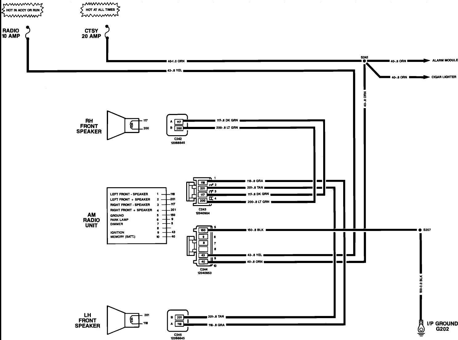
A 2011 Silverado Stereo Wiring Diagram visually depicts the electrical connections and wiring harness for the stereo system in a 2011 Chevrolet Silverado pickup truck. It outlines the specific wiring configurations, color-coded connections, and pinouts necessary to install or repair the stereo system.
This diagram is crucial for ensuring proper electrical connectivity, preventing damage to components, and avoiding potential electrical hazards. It guides technicians and enthusiasts in accurately connecting the stereo head unit, speakers, amplifiers, and other audio components to the vehicle’s electrical system.
The evolution of vehicle stereo systems has significantly impacted the complexity of wiring diagrams. Modern systems integrate advanced features such as Bluetooth connectivity, satellite radio, and GPS navigation, requiring more detailed and comprehensive diagrams to ensure compatibility and functionality.
The essential aspects of a 2011 Silverado Stereo Wiring Diagram provide a comprehensive understanding of the electrical connections and wiring harness for the stereo system in a 2011 Chevrolet Silverado pickup truck. These aspects are crucial for ensuring proper installation, functionality, and troubleshooting of the stereo system.
- Color-Coded Connections: Standardized color-coding simplifies wire identification and matching, ensuring accurate connections between components.
- Pinouts: Diagrams specify the pin configuration of connectors, guiding proper insertion and avoiding damage to components.
- Electrical Specifications: Diagrams include voltage and current requirements, ensuring compatibility between components and preventing electrical overloads.
- Grounding Points: Diagrams indicate proper grounding locations for components, ensuring electrical stability and minimizing noise.
- Speaker Wiring: Diagrams detail speaker wire gauge, polarity, and connection points, optimizing audio performance and preventing damage.
- Amplifier Integration: Diagrams provide guidance on connecting amplifiers to the stereo system, ensuring proper signal amplification and power distribution.
- Accessory Connections: Diagrams include wiring instructions for auxiliary devices such as USB ports, Bluetooth modules, and navigation systems.
- Troubleshooting Guide: Some diagrams incorporate troubleshooting tips and diagnostic procedures, assisting in identifying and resolving electrical issues.
These aspects collectively provide a roadmap for understanding and manipulating the electrical connections of a 2011 Silverado stereo system. They empower technicians, installers, and enthusiasts to make informed decisions, perform accurate installations, and diagnose and repair electrical problems effectively.
Color-Coded Connections
Within the context of a 2011 Silverado Stereo Wiring Diagram, color-coded connections play a crucial role in ensuring accurate and efficient installation of the stereo system. The standardized color-coding scheme simplifies wire identification and matching, enabling technicians to connect components correctly and avoid potential electrical issues. This color-coding system is a critical component of the wiring diagram, providing a clear and concise visual representation of the electrical connections.
For example, the wiring diagram may use specific colors to designate power wires, ground wires, speaker wires, and accessory wires. By adhering to this color-coding scheme, installers can quickly identify the appropriate wires for each connection, reducing the risk of incorrect wiring and potential damage to the stereo system. Additionally, color-coded connections facilitate troubleshooting and repairs, as technicians can easily trace wires and identify potential problems.
The practical significance of understanding color-coded connections extends beyond the installation and maintenance of stereo systems. This concept is widely used in various electrical and electronic applications, including home wiring, industrial automation, and telecommunications. By adhering to standardized color-coding practices, professionals can ensure the safety, reliability, and maintainability of electrical systems.
Pinouts
Within the context of a 2011 Silverado Stereo Wiring Diagram, pinouts play a pivotal role in ensuring the proper installation and functionality of the stereo system. Pinouts are detailed specifications that outline the pin configuration of connectors, providing a clear guide for inserting and connecting components without causing damage.
- Connector Types: Wiring diagrams specify the types of connectors used in the stereo system, such as ISO connectors, DIN connectors, or proprietary connectors. Understanding the connector type is essential for selecting the appropriate mating connector and ensuring a secure connection.
- Pin Assignments: Pinouts define the specific assignment of wires to each pin on a connector. This information is crucial for matching wires correctly and avoiding cross-wiring, which could lead to electrical problems or damage to components.
- Polarity and Signal Flow: Pinouts indicate the polarity and signal flow for each pin. This is particularly important for components such as speakers, where incorrect polarity can result in poor sound quality or damage to the speakers.
- Component Compatibility: Pinouts ensure compatibility between different components in the stereo system. By adhering to the pinout specifications, installers can avoid connecting incompatible components, which could cause electrical issues or system malfunctions.
Understanding pinouts is essential not only for installing a 2011 Silverado stereo system but also for troubleshooting and repairing electrical problems. By referring to the wiring diagram and pinout specifications, technicians can quickly identify and resolve issues related to incorrect connections, faulty components, or damaged wiring.
Electrical Specifications
Within the context of a 2011 Silverado Stereo Wiring Diagram, electrical specifications play a crucial role in ensuring the safe and efficient operation of the stereo system. These specifications provide detailed information about the voltage and current requirements of each component, guiding installers in selecting compatible components and preventing electrical overloads that could damage the system.
- Component Compatibility: Wiring diagrams specify the voltage and current requirements for each component, such as the stereo head unit, speakers, amplifiers, and other accessories. This information ensures that all components are compatible with each other and with the vehicle’s electrical system, preventing potential damage or malfunctions.
- Power Distribution: The wiring diagram outlines the power distribution network for the stereo system, indicating the wire gauge, fuse ratings, and grounding points. This ensures that adequate power is supplied to each component without overloading wires or damaging fuses.
- Speaker Impedance Matching: For speaker connections, the wiring diagram specifies the impedance requirements of the speakers. Matching the speaker impedance to the amplifier’s output impedance is crucial for optimal sound quality and preventing damage to the amplifier.
- Troubleshooting and Repairs: Electrical specifications assist in troubleshooting and repairing electrical problems within the stereo system. By referring to the wiring diagram and specifications, technicians can identify potential issues related to incorrect wiring, faulty components, or electrical overloads, enabling efficient and accurate repairs.
Understanding electrical specifications is essential for ensuring the proper installation, functionality, and longevity of a 2011 Silverado stereo system. By adhering to these specifications, installers and technicians can avoid potential electrical hazards, optimize system performance, and extend the lifespan of the stereo components.
Grounding Points
Within the context of a 2011 Silverado Stereo Wiring Diagram, grounding points play a crucial role in ensuring the proper functionality and longevity of the stereo system. These diagrams specify the designated locations for grounding electrical components, which is essential for maintaining electrical stability, minimizing noise, and preventing potential electrical hazards.
- Electrical Stability: Grounding provides a common reference point for electrical circuits, ensuring that all components operate at the same electrical potential. Without proper grounding, electrical current can flow through unintended paths, leading to system instability, malfunctions, or even electrical shocks.
- Noise Reduction: Grounding helps minimize electrical noise, which can interfere with audio signals and degrade sound quality. By providing a low-resistance path for electrical currents to flow, grounding prevents noise from entering the audio system and ensures clear, undistorted sound reproduction.
- Safety: Proper grounding is essential for electrical safety. It provides a safe path for fault currents to flow in the event of a short circuit or other electrical fault, preventing damage to components or injury to users.
- Component Lifespan: Grounding helps extend the lifespan of electrical components by protecting them from voltage spikes and other electrical transients. By providing a stable electrical environment, grounding reduces stress on components and prevents premature failure.
Understanding grounding points and adhering to the specifications provided in the wiring diagram is crucial for ensuring the reliability, performance, and longevity of a 2011 Silverado stereo system. By properly grounding electrical components, installers can minimize noise, improve electrical stability, enhance safety, and extend the lifespan of the audio system.
Speaker Wiring
Within the context of a 2011 Silverado Stereo Wiring Diagram, speaker wiring plays a critical role in optimizing audio performance and preventing damage to the stereo system’s components. These diagrams detail the speaker wire gauge, polarity, and connection points, providing essential guidance for installers to ensure proper installation and functionality.
The speaker wire gauge, typically measured in American Wire Gauge (AWG), determines the thickness and current-carrying capacity of the wire. The wiring diagram specifies the appropriate gauge for each speaker, considering factors such as speaker impedance, amplifier power, and cable length. Using the correct wire gauge ensures efficient power transfer and minimizes signal loss, resulting in optimal audio quality.
Speaker polarity refers to the positive and negative terminals of the speaker. Incorrect polarity can cause sound cancellation or damage to the amplifier. The wiring diagram clearly indicates the polarity of each speaker connection, guiding installers to match the positive and negative terminals correctly. This ensures proper phasing and accurate sound reproduction.
The connection points, typically located on the speaker terminals and amplifier outputs, must be secure and free of corrosion. The wiring diagram specifies the type of connectors used and provides instructions for proper wire termination, ensuring a reliable electrical connection. Loose or poorly terminated connections can lead to intermittent sound, noise, or damage to the equipment.
Understanding and adhering to the speaker wiring specifications in a 2011 Silverado Stereo Wiring Diagram is crucial for achieving optimal audio performance and preventing potential damage. By following the guidelines provided in the diagram, installers can ensure that the speakers are properly connected, phased, and powered, resulting in a high-quality listening experience and extending the lifespan of the stereo system.
Amplifier Integration
Within the context of a 2011 Silverado Stereo Wiring Diagram, amplifier integration plays a crucial role in optimizing the audio system’s performance and functionality. These diagrams provide detailed instructions on connecting amplifiers to the stereo system, ensuring proper signal amplification and power distribution to the speakers. By understanding and adhering to these guidelines, installers can achieve superior sound quality and enhance the overall listening experience.
- Amplifier Selection: Wiring diagrams specify the compatibility requirements between amplifiers and the stereo system. They indicate the appropriate amplifier power output and impedance matching to ensure optimal performance and prevent damage to components.
- Wiring Configuration: Diagrams detail the wiring configuration for connecting amplifiers to the stereo head unit and speakers. This includes the proper gauge and type of speaker wire, as well as the connection points for power, ground, and signal.
- Power Distribution: The wiring diagram outlines the power distribution network for the amplifiers. It specifies the power source, fuse ratings, and grounding points to ensure adequate and safe power supply.
- Signal Routing: Diagrams provide guidance on routing audio signals from the stereo head unit to the amplifiers and speakers. This includes the use of RCA cables, speaker level inputs, and any necessary signal processing devices.
Understanding and following the amplifier integration guidelines in a 2011 Silverado Stereo Wiring Diagram is essential for maximizing the performance and longevity of the audio system. By properly connecting and configuring the amplifier, installers can optimize signal amplification, ensure efficient power distribution, and achieve the desired sound quality and volume levels.
Accessory Connections
In the context of a 2011 Silverado Stereo Wiring Diagram, accessory connections play a crucial role in extending the functionality and enhancing the user experience of the stereo system. These diagrams provide detailed instructions for integrating auxiliary devices such as USB ports, Bluetooth modules, and navigation systems, allowing for seamless connectivity and integration with external sources and devices.
- USB Port Integration: Wiring diagrams specify the wiring connections for USB ports, enabling the connection of USB flash drives, smartphones, or other compatible devices. This allows for convenient music playback, charging, or data transfer.
- Bluetooth Module Integration: Diagrams guide the installation of Bluetooth modules, providing wireless connectivity to Bluetooth-enabled devices. This enables hands-free calling, music streaming, and control of the stereo system via Bluetooth.
- Navigation System Integration: Wiring diagrams provide instructions for connecting navigation systems to the stereo system. This allows for real-time navigation, traffic updates, and destination input directly through the stereo’s interface.
- Auxiliary Input Integration: Diagrams detail the wiring connections for auxiliary audio inputs, enabling the connection of external audio sources such as MP3 players, CD changers, or satellite radio receivers.
Understanding and following the accessory connection guidelines in a 2011 Silverado Stereo Wiring Diagram is essential for maximizing the versatility and functionality of the audio system. By properly connecting and configuring these auxiliary devices, installers can enhance the user experience, provide convenient connectivity options, and integrate the stereo system with a wider range of external sources and devices.
Troubleshooting Guide
In the context of a 2011 Silverado Stereo Wiring Diagram, the troubleshooting guide serves as an invaluable resource for diagnosing and resolving electrical issues within the stereo system. By providing detailed troubleshooting tips and diagnostic procedures, these diagrams empower installers and technicians to identify and rectify problems efficiently, ensuring optimal performance and user satisfaction.
- Symptom-Based Troubleshooting: Troubleshooting guides often include a list of common symptoms and their potential causes, enabling installers to quickly identify the root of the problem. This systematic approach minimizes guesswork and streamlines the repair process.
- Diagnostic Tests: Diagrams may provide step-by-step instructions for performing diagnostic tests using a multimeter or other tools. These tests help isolate the faulty component or connection, guiding technicians towards a precise solution.
- Wiring Verification: Troubleshooting guides often include instructions for verifying the integrity of wiring connections. By checking for loose connections, shorts, or breaks, technicians can ensure that electrical signals are flowing properly throughout the system.
- Component Replacement Guidance: In cases where a component has failed, troubleshooting guides may provide guidance on identifying the correct replacement part and offer instructions for its installation.
The troubleshooting guide incorporated into a 2011 Silverado Stereo Wiring Diagram is an indispensable tool for both professional installers and DIY enthusiasts. By leveraging the information and procedures outlined in these diagrams, individuals can effectively diagnose and resolve electrical issues, ensuring that their stereo systems operate at their optimal performance levels.


![[DIAGRAM] 2011 Silverado Radio Wiring Diagram Speaker](https://lh3.googleusercontent.com/proxy/lRd2Zc9FAM9Zu2DG3TZJdRZehOr9bxA3eHnW8OiJgn012p3aXabt30EvEeG1Gd97vBTAC2_Z9D1rMjrl9Qtcvd9jc2vwcOO0d_iMHb3znDBLCYuviQDs2JMt01swtyWpgoqr9AETugTjosnie-WjJt-19PEVTmZZR_0h0Is=s0-d)


Related Posts


