A “2004 Ford Explorer Radio Wiring Diagram” is a technical document that outlines the electrical connections for the radio system in a 2004 Ford Explorer vehicle. It provides a visual representation of the wires, connectors, and components involved in the radio’s operation.
Wiring diagrams are essential for troubleshooting electrical problems, installing aftermarket radios, and understanding the overall functionality of the radio system. They provide a detailed map of the electrical connections, allowing technicians and enthusiasts to trace circuits, identify faults, and diagnose issues.
A key historical development in automotive wiring diagrams was the standardization of color-coded wires. Prior to this, wires were often labeled with numbers or letters, which could be confusing and difficult to follow. The introduction of standardized color-coding made it much easier to identify and trace wires, improving the efficiency and accuracy of electrical repairs.
In the following sections, we will explore the key features, benefits, and applications of “2004 Ford Explorer Radio Wiring Diagrams,” providing detailed information and practical examples to enhance your understanding of this important technical resource.
Understanding the essential aspects of a “2004 Ford Explorer Radio Wiring Diagram” is crucial for troubleshooting, installation, and maintenance tasks. These key aspects provide insights into the electrical connections, components, and functionality of the radio system.
- Color Coding: Standardized colors for wires, simplifying identification.
- Connector Types: Different types of connectors used to join wires.
- Wire Gauge: Thickness of wires, indicating current-carrying capacity.
- Component Locations: Placement of radio, speakers, and other components.
- Power and Ground Connections: Essential connections for powering the radio.
- Antenna Connections: Wiring for connecting the radio to the antenna.
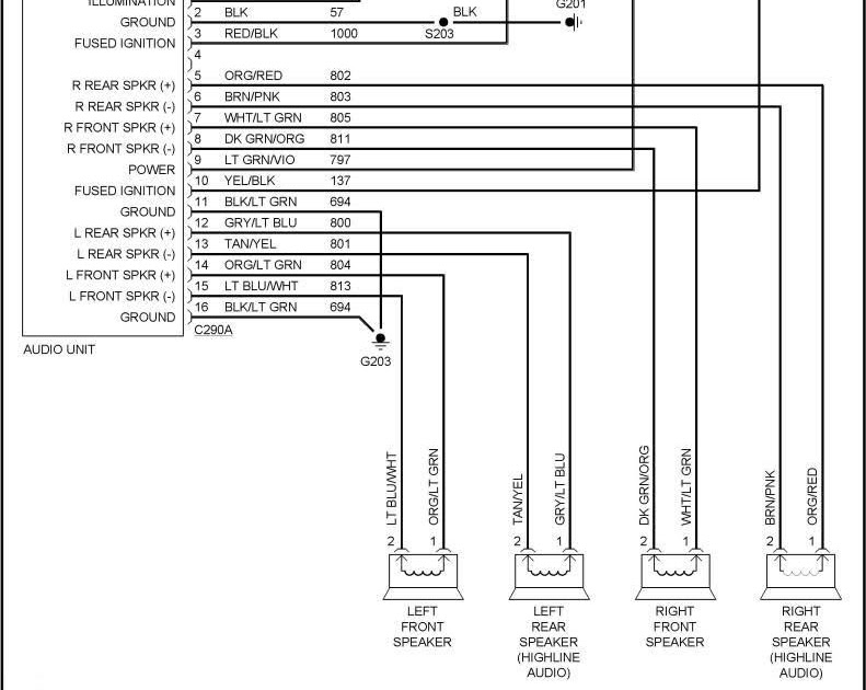
- Speaker Connections: Wiring for connecting the radio to the speakers.
- Accessory Connections: Optional connections for integrating external devices.
These aspects are interconnected and provide a comprehensive understanding of the radio wiring diagram. For instance, color coding helps identify the correct wires for power, ground, and speaker connections. Connector types ensure secure and reliable connections between wires and components. Understanding wire gauge is crucial for selecting appropriate wires that can handle the electrical load. Knowing the component locations aids in troubleshooting and maintenance tasks. Overall, a thorough grasp of these aspects empowers individuals to work with “2004 Ford Explorer Radio Wiring Diagrams” effectively and confidently.
Color Coding
Within the context of a “2004 Ford Explorer Radio Wiring Diagram,” color coding plays a vital role in simplifying the identification of wires. This standardized system assigns specific colors to different types of wires, making it easier to trace connections, troubleshoot issues, and perform installations or repairs.
- Power Wires: Typically red or yellow, these wires carry power from the battery to the radio.
- Ground Wires: Usually black or brown, ground wires provide a path for electrical current to return to the battery.
- Speaker Wires: Speaker wires come in pairs, with each pair carrying signals to a specific speaker. Common colors include white, gray, green, and purple.
- Accessory Wires: These wires, often blue or orange, are used to connect external devices such as amplifiers or CD changers.
The standardized color coding in “2004 Ford Explorer Radio Wiring Diagrams” ensures consistency across different vehicle models and trim levels. It reduces the risk of misconnections and makes it easier for technicians and enthusiasts to work on the radio system. By following the color-coded wires, individuals can quickly identify the correct connections for power, ground, speakers, and accessories, streamlining the installation and troubleshooting processes.
Connector Types
When examining a “2004 Ford Explorer Radio Wiring Diagram,” one crucial aspect to consider is the variety of connector types used to join wires. These connectors play a critical role in ensuring secure and reliable electrical connections within the radio system.
- Butt Connectors: Simple and commonly used connectors for joining two wires end-to-end. Ideal for basic splicing and repairs.
- Crimp Connectors: Similar to butt connectors but provide a more secure connection by crimping the connector around the wires.
- Splice Connectors: Designed to tap into an existing wire without cutting it. Useful for adding accessories or troubleshooting.
- Terminal Connectors: Used to connect wires to terminals on components such as the radio or speakers.
Understanding the different types of connectors is essential when working with a “2004 Ford Explorer Radio Wiring Diagram.” By choosing the appropriate connector for the specific application, individuals can ensure proper electrical connections, minimize the risk of short circuits or other electrical issues, and maintain the integrity of the radio system.
Wire Gauge
When examining a “2004 Ford Explorer Radio Wiring Diagram,” understanding wire gauge is crucial. Wire gauge measures the thickness of wires, which directly relates to their current-carrying capacity. Thicker wires can handle higher currents without overheating or causing damage, while thinner wires are suitable for lower currents.
In the context of a “2004 Ford Explorer Radio Wiring Diagram,” wire gauge is a critical component. The radio system’s power consumption and speaker impedance determine the appropriate wire gauge for each connection. Using wires with insufficient gauge can lead to voltage drops, power loss, and potential overheating, compromising the radio’s performance and longevity.
For instance, the power wire connecting the battery to the radio typically requires a thicker gauge wire to handle the higher current draw. Conversely, speaker wires can use a thinner gauge wire as they carry lower currents. By adhering to the specified wire gauge recommendations in the wiring diagram, individuals can ensure the radio system operates safely and efficiently.
Understanding wire gauge and its relation to current-carrying capacity empowers individuals to make informed decisions when selecting and installing wires for their “2004 Ford Explorer” radio system. This knowledge helps prevent electrical issues, optimizes performance, and ensures the longevity of the radio and its components.
Component Locations
Within the context of a “2004 Ford Explorer Radio Wiring Diagram,” understanding the placement of components, including the radio, speakers, and other related elements, is crucial. This knowledge is pivotal in guiding the wiring process, ensuring optimal performance, and facilitating troubleshooting efforts.
- Radio Placement: The radio is typically mounted in the dashboard, providing easy access to controls and display. Its location determines the length and routing of wiring harnesses connecting it to other components and power sources.
- Speaker Placement: Speakers are strategically positioned throughout the vehicle to deliver immersive audio. Front speakers are often installed in the doors or dashboard, while rear speakers are commonly mounted in the parcel shelf or side panels.
- Antenna Placement: The antenna, responsible for receiving radio signals, is typically mounted on the roof or rear of the vehicle. Its placement affects signal strength and reception quality.
- Amplifier Placement: If an external amplifier is used to boost audio power, its placement must consider factors such as heat dissipation, wire routing, and accessibility for adjustments.
By understanding the placement of these components, individuals can effectively plan and execute the wiring process outlined in a “2004 Ford Explorer Radio Wiring Diagram.” Proper component placement optimizes signal transmission, minimizes interference, and ensures the radio system operates at its full potential. Furthermore, it aids in troubleshooting by providing insights into potential issues related to wiring, connections, or component malfunctions.
Power and Ground Connections
Power and ground connections are crucial aspects of a “2004 Ford Explorer Radio Wiring Diagram,” providing the electrical foundation for the radio system to operate. Understanding these connections is essential for successful installation, troubleshooting, and maintenance tasks.
- Battery Connection: The radio receives power directly from the vehicle’s battery, typically through a dedicated power wire. This connection must be secure and of sufficient gauge to handle the radio’s current draw.
- Ground Connection: A proper ground connection provides a path for electrical current to return to the battery, completing the electrical circuit. Ground wires are typically connected to metal components of the vehicle’s chassis.
- Fuse Protection: Fuses are incorporated into the power circuit to protect the radio and wiring from electrical overloads or short circuits. Blown fuses indicate a potential issue that requires investigation.
- Wiring Harness: A wiring harness consolidates and simplifies the power and ground connections between the radio and other components. It ensures a standardized and organized connection process.
These power and ground connections are intertwined and form the backbone of the radio system’s electrical infrastructure. Proper installation and maintenance of these connections ensure reliable operation, prevent electrical malfunctions, and maximize the performance of the radio system in a “2004 Ford Explorer.”
Antenna Connections
Within the realm of “2004 Ford Explorer Radio Wiring Diagram,” antenna connections play a fundamental role in establishing communication between the radio and the outside world. These connections enable the radio to receive signals from broadcast towers, providing access to a wide range of audio content.
- Antenna: The antenna, typically mounted on the roof or rear of the vehicle, captures radio waves and converts them into electrical signals.
- Coaxial Cable: A coaxial cable transmits the electrical signals from the antenna to the radio. It consists of a central conductor surrounded by insulation and a braided shield.
- Connectors: Connectors on the antenna and the radio establish a secure electrical connection, ensuring proper signal transfer.
- Grounding: A proper ground connection provides a path for electrical current to complete the circuit, improving signal reception and reducing noise.
Understanding these components and their interconnections is crucial for troubleshooting reception issues, optimizing signal strength, and ensuring the seamless operation of the radio system in a “2004 Ford Explorer.” Proper antenna connections guarantee clear and reliable audio, enhancing the overall listening experience within the vehicle.
Speaker Connections
Within the intricacies of “2004 Ford Explorer Radio Wiring Diagram,” speaker connections emerge as a critical aspect, dictating the seamless transmission of audio signals from the radio to the speakers. Understanding these connections is pivotal in ensuring optimal sound quality and immersive listening experiences.
- Speaker Wires: Electrical conduits that carry audio signals from the radio to the speakers. Typically color-coded for easy identification and proper polarity.
- Speaker Terminals: Connection points on the radio and speakers where speaker wires are attached. Ensuring secure and low-resistance connections is crucial.
- Speaker Impedance: Electrical resistance of the speakers, which must match the radio’s output impedance for efficient power transfer and optimal sound reproduction.
- Speaker Placement: Strategic positioning of speakers within the vehicle’s cabin. Proper placement optimizes sound dispersion, minimizes acoustic interference, and enhances the overall listening experience.
These facets of speaker connections underscore their fundamental role in the “2004 Ford Explorer Radio Wiring Diagram.” Proper understanding and execution of these connections ensure accurate signal transmission, eliminate audio distortions, and maximize the capabilities of the radio system. Ultimately, meticulous attention to speaker connections contributes to an elevated acoustic environment, enriching the driving experience with high-fidelity audio.
Accessory Connections
Within the context of “2004 Ford Explorer Radio Wiring Diagram,” accessory connections play a crucial role in expanding the functionality of the radio system by allowing the integration of external devices. These connections provide the electrical pathways for seamless communication and control between the radio and various auxiliary components, enhancing the overall driving experience.
- Auxiliary Input: Enables the connection of external audio sources such as MP3 players or portable music devices, allowing users to enjoy their personal music collections through the vehicle’s audio system.
- Bluetooth Connectivity: Provides wireless communication between the radio and Bluetooth-enabled devices like smartphones, enabling hands-free calling, audio streaming, and control of music playback.
- Satellite Radio Tuner: Facilitates the integration of satellite radio modules, granting access to a wide variety of audio channels and programming.
- Rear Seat Entertainment System: Allows the connection of additional audio and video components to entertain rear-seat passengers, enhancing overall comfort and enjoyment during long journeys.
These accessory connections underscore the adaptability and versatility of the “2004 Ford Explorer Radio Wiring Diagram.” By providing the means to integrate external devices, the radio system transforms into a central hub for entertainment, communication, and convenience, enriching the driving experience with a multitude of options and features.


Related Posts


