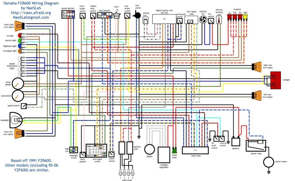
A “2000 Yamaha R6 Wiring Diagram” is a comprehensive technical document that provides detailed schematics of the electrical system in a 2000 Yamaha R6 motorcycle.
This diagram is an essential resource for troubleshooting electrical problems, understanding the motorcycle’s wiring system, and making modifications or repairs. It includes information on wire colors, terminals, connectors, and component locations, allowing technicians to diagnose and resolve electrical issues efficiently.
The 2000 Yamaha R6 Wiring Diagram has played a crucial role in maintaining and servicing Yamaha R6 motorcycles, ensuring their proper operation and safety. Its relevance extends to both professional mechanics and motorcycle enthusiasts who seek to understand and maintain their own machines.
The 2000 Yamaha R6 Wiring Diagram, a detailed technical document, plays a crucial role in maintaining and servicing the electrical system of the motorcycle. Understanding its key aspects is essential for effective troubleshooting, modifications, and repairs.
- Accuracy: The diagram provides precise information on wire colors, terminals, connectors, and component locations, ensuring accurate diagnosis and resolution of electrical issues.
- Comprehensiveness: It encompasses the entire electrical system, offering a complete view of all electrical components and their interconnections.
- Troubleshooting: The diagram aids in identifying faulty components, tracing wire paths, and understanding the flow of electrical signals.
- Modifications: It serves as a guide for modifying or adding electrical accessories, ensuring compatibility and proper functioning.
- Repairs: The diagram provides the necessary information for repairing electrical faults, such as broken wires, damaged connectors, or malfunctioning components.
- Maintenance: It assists in routine maintenance tasks, such as checking wire connections, inspecting insulation, and identifying potential problems.
- Safety: Understanding the wiring diagram is crucial for ensuring the safe operation of the motorcycle, preventing electrical hazards and potential accidents.
- Performance: The diagram can be used to optimize electrical system performance by identifying areas for improvement, such as reducing resistance or upgrading components.
These aspects collectively highlight the importance of the 2000 Yamaha R6 Wiring Diagram as an indispensable tool for maintaining, troubleshooting, and modifying the electrical system of the motorcycle, ensuring its reliable and safe operation.
Accuracy
Accuracy is a crucial aspect of the 2000 Yamaha R6 Wiring Diagram, providing precise information on wire colors, terminals, connectors, and component locations. This accuracy is essential for effective troubleshooting, modifications, and repairs, ensuring the proper functioning and safety of the motorcycle’s electrical system.
-
Wire Color Identification:
The diagram accurately represents the color coding of wires, enabling technicians to easily identify and trace specific circuits throughout the electrical system. This facilitates quick and accurate diagnosis of electrical faults. -
Terminal and Connector Specifications:
Precise information on terminal types and connector pinouts is provided, ensuring proper mating and connection of components. This accuracy prevents misconnections and potential damage to the electrical system. -
Component Location Identification:
The diagram clearly indicates the location of all electrical components, including sensors, relays, fuses, and modules. This aids in efficient troubleshooting and replacement of faulty parts, reducing downtime and maintenance costs. -
Grounding Points:
Accurate grounding information is crucial for proper electrical system operation. The diagram provides precise locations of grounding points, ensuring a secure and reliable electrical connection to the motorcycle’s frame.
The accuracy of the 2000 Yamaha R6 Wiring Diagram empowers technicians and enthusiasts with the knowledge and confidence to diagnose, repair, and modify the electrical system effectively. It serves as a valuable tool for maintaining the motorcycle’s performance, reliability, and safety.
Comprehensiveness
The comprehensiveness of the 2000 Yamaha R6 Wiring Diagram sets it apart as a valuable tool for understanding and maintaining the motorcycle’s electrical system. It offers a complete overview of all electrical components and their interconnections, empowering technicians and enthusiasts to troubleshoot, repair, and modify the system effectively.
-
Component Identification:
The diagram provides a comprehensive list of all electrical components, including their names, locations, and functions. This aids in identifying and locating specific components for maintenance, troubleshooting, or replacement. -
Circuit Tracing:
The diagram clearly illustrates the flow of electrical current through the entire system, making it easy to trace circuits and identify potential problems. This facilitates rapid diagnosis of electrical faults and ensures proper system operation. -
Connector Diagrams:
Detailed diagrams of electrical connectors are included, providing information on pinouts, wire colors, and connector types. This information is essential for ensuring proper mating and connection of components, preventing misconnections and potential damage. -
Grounding Points:
The diagram accurately identifies all grounding points in the electrical system. This information is crucial for maintaining proper grounding, which is essential for electrical system stability, component protection, and noise reduction.
The comprehensiveness of the 2000 Yamaha R6 Wiring Diagram empowers users with a thorough understanding of the motorcycle’s electrical system. It serves as a comprehensive reference for troubleshooting, maintenance, and modifications, ensuring the reliable and safe operation of the motorcycle.
Troubleshooting
The 2000 Yamaha R6 Wiring Diagram is an essential tool for troubleshooting electrical problems in the motorcycle. It provides a comprehensive overview of the electrical system, including wire colors, terminal connections, and component locations. This information is critical for identifying faulty components, tracing wire paths, and understanding the flow of electrical signals.
For example, if a technician encounters an electrical issue such as a non-functioning headlight, they can refer to the wiring diagram to identify the circuit responsible for the headlight. The diagram will provide information on the wire colors, terminal connections, and component locations involved in that circuit. This allows the technician to trace the circuit, identify any loose connections or damaged wires, and pinpoint the faulty component.
The ability to troubleshoot electrical problems using the wiring diagram is essential for maintaining the proper functioning and safety of the motorcycle. Electrical faults can lead to a variety of issues, including reduced performance, unreliable operation, and even potential hazards. By understanding the electrical system and being able to identify and repair faults, technicians and enthusiasts can ensure that their Yamaha R6 operates safely and reliably.
Modifications
The 2000 Yamaha R6 Wiring Diagram plays a crucial role in facilitating modifications to the motorcycle’s electrical system. It provides a comprehensive overview of the electrical system, including wire colors, terminal connections, and component locations. This information is essential for ensuring compatibility and proper functioning when adding or modifying electrical accessories.
For example, if a rider wishes to install heated grips on their Yamaha R6, they can refer to the wiring diagram to identify the appropriate circuit and connection points. The diagram will provide information on the wire colors, terminal connections, and component locations involved in that circuit, allowing the rider to safely and correctly connect the heated grips to the motorcycle’s electrical system.
The ability to use the wiring diagram as a guide for modifications is particularly important for ensuring the compatibility and proper functioning of electrical accessories. Electrical accessories that are not properly connected or compatible with the motorcycle’s electrical system can lead to a variety of issues, including reduced performance, unreliable operation, and even potential hazards.
By understanding the electrical system and being able to make modifications using the wiring diagram, riders can customize their Yamaha R6 to meet their specific needs and preferences, while ensuring that the electrical accessories are compatible and functioning properly.
Repairs
The 2000 Yamaha R6 Wiring Diagram serves as a comprehensive guide for repairing electrical faults, providing detailed information on wire colors, terminal connections, and component locations. This information is critical for identifying and repairing a wide range of electrical issues, ensuring the proper functioning and safety of the motorcycle.
For example, if a rider encounters an electrical problem such as a non-functioning turn signal, they can refer to the wiring diagram to identify the circuit responsible for the turn signal. The diagram will provide information on the wire colors, terminal connections, and component locations involved in that circuit. This allows the rider to trace the circuit, identify any loose connections or damaged wires, and pinpoint the faulty component. Once the faulty component is identified, the rider can use the wiring diagram to determine the correct replacement part and follow the instructions to repair the electrical fault.
The ability to use the wiring diagram for repairs is essential for maintaining the proper functioning and safety of the Yamaha R6. Electrical faults can lead to a variety of issues, including reduced performance, unreliable operation, and even potential hazards. By understanding the electrical system and being able to repair faults using the wiring diagram, riders can ensure that their Yamaha R6 operates safely and reliably.
Maintenance
The 2000 Yamaha R6 Wiring Diagram plays a crucial role in facilitating routine maintenance tasks, providing detailed information on wire colors, terminal connections, and component locations. This information is essential for ensuring the proper functioning and safety of the motorcycle’s electrical system.
For example, the wiring diagram can be used to check wire connections for tightness and corrosion, inspect insulation for damage, and identify potential problems such as loose terminals or damaged wires. By regularly performing these maintenance tasks using the wiring diagram as a guide, riders can proactively identify and address potential electrical issues before they become major problems.
Regular maintenance is essential for extending the life of the motorcycle’s electrical system and ensuring its reliable operation. The 2000 Yamaha R6 Wiring Diagram provides the necessary information to perform these maintenance tasks effectively, contributing to the overall safety and performance of the motorcycle.
Safety
The 2000 Yamaha R6 Wiring Diagram plays a vital role in ensuring the safe operation of the motorcycle by providing a comprehensive overview of the electrical system, including wire colors, terminal connections, and component locations. Understanding this diagram is crucial for identifying and resolving electrical issues, preventing potential hazards, and maintaining the overall safety of the motorcycle.
Electrical faults can manifest in various forms, such as loose connections, damaged wires, or malfunctioning components. These faults can lead to a range of problems, including reduced performance, unreliable operation, and in severe cases, electrical fires or accidents. By understanding the wiring diagram and being able to identify and repair electrical faults, riders can proactively address these issues, ensuring the safe and reliable operation of their Yamaha R6.
For example, a loose connection in the wiring harness can lead to intermittent electrical problems, such as flickering lights or stalling. By referring to the wiring diagram, a technician can locate the loose connection and securely tighten it, resolving the issue and preventing potential hazards.
Another example is a damaged wire in the ignition system. A damaged wire can cause the engine to fail to start or run erratically. By using the wiring diagram to trace the ignition circuit, a technician can identify the damaged wire and replace it, restoring the proper functioning of the ignition system and ensuring the safe operation of the motorcycle.
In summary, understanding the 2000 Yamaha R6 Wiring Diagram is paramount for ensuring the safety of the motorcycle and its rider. By providing detailed information on the electrical system, the wiring diagram empowers riders and technicians to identify and repair electrical faults, preventing potential hazards and maintaining the reliable operation of the motorcycle.
Performance
The 2000 Yamaha R6 Wiring Diagram plays a crucial role in optimizing electrical system performance, providing a detailed roadmap of the electrical system and enabling the identification of areas for improvement. By understanding the electrical system and its components, technicians and enthusiasts can make informed decisions to enhance performance.
One key aspect of optimizing performance is reducing resistance in the electrical system. Resistance can hinder the flow of electrical current, leading to reduced power output and inefficiencies. By analyzing the wiring diagram, technicians can identify areas where resistance may be an issue, such as undersized wires or poor connections. Upgrading to larger gauge wires or replacing faulty connectors can significantly reduce resistance, allowing for improved current flow and enhanced performance.
Another aspect is upgrading electrical components. The 2000 Yamaha R6 Wiring Diagram provides valuable information on the compatibility and specifications of electrical components, allowing users to identify opportunities for upgrades. For example, upgrading to a higher-performance ignition coil can improve spark intensity and combustion efficiency, resulting in increased power and smoother engine operation.
By leveraging the 2000 Yamaha R6 Wiring Diagram, technicians and enthusiasts can optimize the electrical system for improved performance, reliability, and efficiency. It serves as a comprehensive tool for identifying areas of improvement, making informed decisions, and implementing upgrades to enhance the overall riding experience.


Related Posts


