2000 Ford Mustang Radio Wiring Diagram is a detailed representation of the electrical connections within the audio system of a 2000 Ford Mustang. It outlines the specific wires, connectors, and terminals required for the proper installation, repair, and maintenance of the vehicle’s radio.
This diagram is crucial for understanding the electrical layout of the radio system, enabling technicians, car enthusiasts, and DIYers to diagnose and troubleshoot issues, such as loss of power, distorted sound, or non-functional buttons. A comprehensive wiring diagram provides a visual guide to identify the correct wires and connections, ensuring a reliable and secure installation.
The development of standardized wiring diagrams has significantly simplified the process of automotive electrical troubleshooting. They serve as valuable resources for both professionals and individuals working on vehicle repairs and upgrades. Understanding the wiring diagram is essential before commencing any modifications or repairs to the radio system, helping to prevent electrical damage and potential safety hazards.
Understanding the essential aspects of “2000 Ford Mustang Radio Wiring Diagram” is crucial for anyone working on the electrical system of their vehicle. This diagram provides a visual representation of the electrical connections within the audio system, making it an invaluable tool for troubleshooting, repair, and installation.
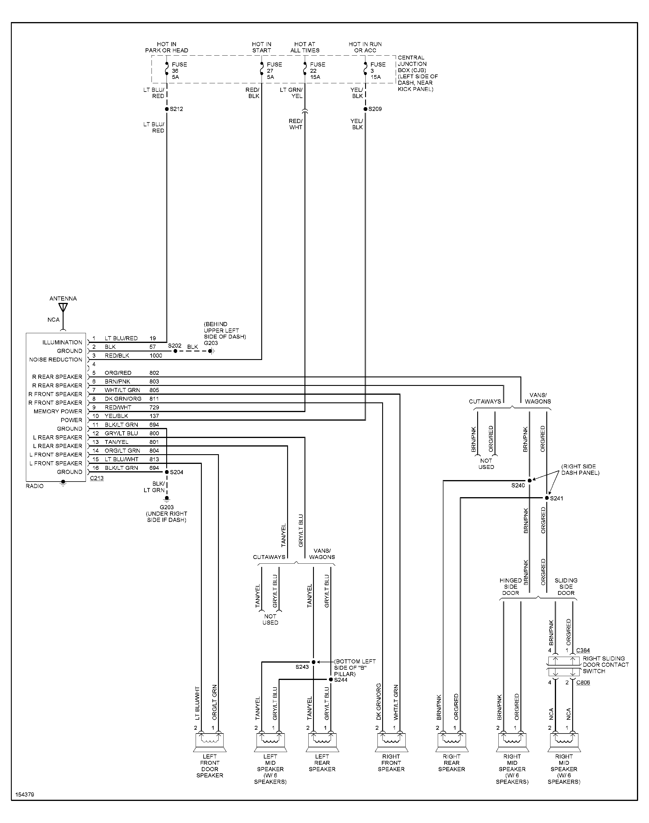
- Components: The diagram identifies all the components of the radio system, including the radio itself, speakers, amplifier, and any other connected devices.
- Wiring: It shows the specific wires used to connect each component, including their color coding and gauge.
- Connectors: The diagram indicates the types of connectors used to join the wires, such as crimp connectors, solder joints, or terminal blocks.
- Power: It outlines the power supply to the radio system, including the source of power, the fuse that protects the circuit, and the ground connection.
- Signal: The diagram shows the signal path from the source (such as a CD player or radio tuner) to the amplifier and speakers.
- Grounding: Proper grounding is essential for the electrical system to function correctly, and the diagram indicates the grounding points for the radio system.
- Troubleshooting: The diagram aids in troubleshooting electrical problems by providing a visual reference to identify potential issues.
- Installation: It serves as a guide for installing a new radio or other components into the vehicle’s audio system.
- Modification: The diagram can assist in modifying the audio system, such as adding an amplifier or upgrading the speakers.
- Safety: Understanding the electrical connections through the wiring diagram helps ensure safe installation and operation of the radio system.
These aspects collectively provide a comprehensive understanding of the electrical layout of the 2000 Ford Mustang radio system, enabling technicians, car enthusiasts, and DIYers to work on it confidently and effectively.
Components
In the context of the “2000 Ford Mustang Radio Wiring Diagram,” identifying the components of the radio system is crucial because it forms the foundation for understanding the electrical connections and signal flow within the system. The diagram serves as a roadmap, allowing technicians and DIYers to visualize the relationship between each component and its corresponding wires, connectors, and terminals.
For instance, the diagram shows how the radio head unit connects to the speakers through speaker wires, and how the amplifier receives power and signal from the head unit. This understanding helps in troubleshooting issues such as no sound output or distorted audio.
Furthermore, the diagram provides insights into the integration of other connected devices, such as CD players, auxiliary inputs, or Bluetooth modules. By identifying the specific wires and connections required for these devices, the diagram enables users to expand the functionality of their audio system.
In summary, the identification of components in the “2000 Ford Mustang Radio Wiring Diagram” is a critical aspect that allows users to comprehend the system’s electrical layout, diagnose problems, and make informed decisions regarding modifications or upgrades.
Wiring
Within the context of the “2000 Ford Mustang Radio Wiring Diagram,” the wiring plays a critical role in establishing the electrical connections between various components of the radio system. It serves as the conduit for transmitting power, audio signals, and control commands throughout the system, enabling the functionality of each component.
The color coding and gauge of the wires are crucial aspects of the wiring diagram. Color coding provides a standardized method for identifying the function of each wire, making it easier to trace connections and troubleshoot issues. The wire gauge, on the other hand, determines the current-carrying capacity of the wire, ensuring that it can safely handle the electrical load of the connected components.
For example, the wiring diagram specifies that the power wire for the radio is typically red or yellow, while the ground wire is black or brown. This color coding helps technicians quickly identify these essential connections and avoid mistakes during installation or repairs.
Understanding the wiring is also essential for modifications or upgrades to the radio system. By referring to the diagram, users can determine the appropriate wires to tap into for adding an amplifier or installing new speakers. This understanding helps ensure that the modifications are done correctly, maintaining the integrity and performance of the system.
In summary, the wiring information provided in the “2000 Ford Mustang Radio Wiring Diagram” is a critical component for comprehending the electrical connections within the radio system. It enables users to troubleshoot issues, make informed modifications, and ensure the proper functioning of the system.
Connectors
Within the context of the “2000 Ford Mustang Radio Wiring Diagram,” the connectors play a critical role in establishing secure and reliable electrical connections between wires and components. They provide a means to join wires together, ensuring the proper flow of electrical signals and power throughout the radio system. The diagram specifies the types of connectors used at each connection point, such as crimp connectors, solder joints, or terminal blocks.
Crimp connectors are commonly used in automotive electrical systems due to their ease of use and reliability. They involve crimping a metal sleeve around the stripped ends of two or more wires, creating a secure mechanical and electrical connection. Solder joints, on the other hand, provide a more permanent connection by melting solder onto the twisted ends of wires, forming a strong bond. Terminal blocks offer a convenient and reusable method for connecting multiple wires to a single point, using screw terminals or spring-loaded clamps.
Understanding the types of connectors used in the “2000 Ford Mustang Radio Wiring Diagram” is essential for proper installation, maintenance, and troubleshooting of the radio system. By using the correct connectors and following the specified wiring diagram, users can ensure that electrical connections are secure, preventing potential issues such as loose connections, shorts, or malfunctions.
For example, if a speaker is not producing sound, checking the connections at the speaker terminals using the wiring diagram can help identify any loose or damaged connectors. Similarly, when installing an aftermarket radio, the wiring diagram provides guidance on the appropriate connectors to use for connecting the radio to the vehicle’s electrical system.
In summary, the connectors specified in the “2000 Ford Mustang Radio Wiring Diagram” are critical components for establishing reliable electrical connections within the radio system. Understanding the types of connectors used and their proper installation is essential for maintaining a functional and trouble-free audio system.
Power
In the context of the “2000 Ford Mustang Radio Wiring Diagram,” understanding the power supply is crucial for ensuring the proper functioning of the radio system. The diagram outlines the source of power, the fuse that protects the circuit, and the ground connection, providing a comprehensive overview of the electrical system.
-
Power Source
The diagram identifies the source of power for the radio system, which is typically the vehicle’s battery. It specifies the wire that connects the battery to the radio and the fuse that protects this connection.
-
Fuse Protection
The wiring diagram indicates the location and amperage rating of the fuse that protects the radio circuit. This fuse is designed to blow in the event of a power surge or short circuit, safeguarding the radio and other electrical components from damage.
-
Ground Connection
A proper ground connection is essential for completing the electrical circuit and preventing electrical noise. The diagram shows the location of the ground connection point, which is typically a metal chassis or frame of the vehicle.
-
Wiring Color Coding
The wiring diagram uses color-coded wires to differentiate between power, ground, and signal connections. This color coding simplifies the installation and troubleshooting process, ensuring that the radio is connected correctly.
Understanding the power supply aspects of the “2000 Ford Mustang Radio Wiring Diagram” enables technicians and DIYers to diagnose and resolve electrical issues, ensuring that the radio system operates reliably and safely.
Signal
In the context of the “2000 Ford Mustang Radio Wiring Diagram,” understanding the signal path is crucial for comprehending the flow of audio signals within the radio system. The diagram outlines the connections between the source (such as a CD player or radio tuner), the amplifier, and the speakers, providing a visual representation of the signal flow.
The signal path begins at the source, which generates the audio signal. This signal is then transmitted through the wiring harness to the amplifier, where it is amplified to increase its power. The amplified signal is then sent to the speakers, which convert the electrical signal back into sound waves.
Understanding the signal path is essential for troubleshooting audio issues. For example, if there is no sound output from the speakers, checking the connections along the signal path can help identify any loose wires or faulty components. Additionally, understanding the signal path is important when making modifications to the audio system, such as adding an equalizer or upgrading the speakers.
The “2000 Ford Mustang Radio Wiring Diagram” provides a clear and concise representation of the signal path, enabling users to diagnose and resolve issues, as well as make informed decisions about modifications to their audio system.
Grounding
Within the context of the “2000 Ford Mustang Radio Wiring Diagram,” grounding plays a crucial role in ensuring the proper functioning and safety of the electrical system, particularly for the radio system. Grounding provides a common reference point for electrical circuits, allowing current to flow properly and preventing electrical noise and malfunctions.
-
Chassis Grounding
The radio system is grounded to the chassis of the vehicle, which provides a stable and low-resistance path for current to flow. This grounding point is typically indicated in the wiring diagram and involves connecting a wire from the radio to a metal part of the chassis.
-
Battery Grounding
The negative terminal of the vehicle’s battery is also a common grounding point. Connecting the radio system to this point ensures that all electrical components share a common reference voltage, reducing the risk of ground loops and electrical interference.
-
Signal Grounding
In addition to the power ground, the wiring diagram may also indicate grounding points for signal wires. These grounds provide a reference point for audio and other signals, minimizing noise and ensuring proper signal transmission.
-
Safety Implications
Proper grounding is crucial for the safety of the electrical system. Without proper grounding, electrical faults can occur, potentially leading to component damage, electrical fires, or even personal injury.
Understanding the grounding aspects of the “2000 Ford Mustang Radio Wiring Diagram” is essential for ensuring a reliable and safe electrical system. By following the grounding points indicated in the diagram, technicians and DIYers can minimize electrical issues, improve audio quality, and maintain the integrity of the vehicle’s electrical components.
Troubleshooting
Within the context of the “2000 Ford Mustang Radio Wiring Diagram,” troubleshooting is a critical aspect that leverages the diagram’s visual representation to diagnose and resolve electrical issues within the radio system. The diagram provides a comprehensive overview of the electrical connections, enabling users to identify potential problem areas based on symptoms and observations.
For instance, if the radio is not receiving power, the wiring diagram guides the user in checking the power supply connections, including the fuse and ground wire. By following the diagram, users can systematically eliminate potential causes and pinpoint the exact location of the fault.
Additionally, the diagram assists in diagnosing signal-related issues, such as distorted audio or speaker malfunctions. By analyzing the signal path outlined in the diagram, users can identify loose connections or faulty components that may be affecting the signal transmission.
Overall, the troubleshooting capabilities of the “2000 Ford Mustang Radio Wiring Diagram” empower users to approach electrical problems with a structured and methodical approach, reducing guesswork and minimizing the time and effort required for repairs.
Installation
Within the context of the “2000 Ford Mustang Radio Wiring Diagram,” the installation aspect plays a critical role in understanding how to integrate new audio components into the vehicle’s system. The wiring diagram provides a visual guide that outlines the electrical connections necessary for successful installation.
The diagram serves as a roadmap for installers, detailing the specific wires that need to be connected to power the new radio or component, as well as the signal paths for audio transmission. By following the diagram, users can ensure that the new components are properly integrated into the existing electrical system, avoiding potential issues such as shorts, blown fuses, or malfunctioning components.
For instance, when installing an aftermarket radio, the wiring diagram guides the user in identifying the correct wires for power, ground, speakers, and any additional features such as steering wheel controls or Bluetooth connectivity. The diagram ensures that the new radio is compatible with the vehicle’s electrical system and functions as intended.
Understanding the installation aspect of the “2000 Ford Mustang Radio Wiring Diagram” is essential for anyone looking to upgrade or modify their vehicle’s audio system. By leveraging the diagram, users can confidently tackle installation projects, saving time, effort, and potential headaches.
Modification
In the context of “2000 Ford Mustang Radio Wiring Diagram,” the aspect of modification empowers users to customize and enhance their vehicle’s audio system. The diagram provides a visual guide to the electrical connections, enabling informed decision-making and successful implementation of modifications.
-
Upgrading Speakers
The wiring diagram assists in upgrading the factory speakers with aftermarket options. It outlines the speaker connections, ensuring proper polarity and impedance matching for optimal audio performance.
-
Adding an Amplifier
For increased audio power and clarity, the diagram guides the user in adding an amplifier to the system. It details the power and signal connections, ensuring compatibility with the existing electrical infrastructure.
-
Integrating Subwoofers
To enhance bass response, the wiring diagram provides guidance on integrating subwoofers into the audio system. It outlines the necessary connections for power, signal, and remote turn-on.
-
Customizing Audio Controls
The diagram assists in modifying audio controls, such as adding steering wheel controls or integrating a Bluetooth module. It outlines the wiring connections and compatibility requirements for seamless integration.
Understanding the modification aspect of the “2000 Ford Mustang Radio Wiring Diagram” empowers users to tailor their audio system to their specific preferences and requirements. By following the diagram, users can confidently undertake audio system modifications, enhancing their driving experience with improved sound quality and personalized audio features.
Safety
Within the context of “2000 Ford Mustang Radio Wiring Diagram,” safety plays a paramount role in ensuring the proper functioning and longevity of the installed audio system. The wiring diagram serves as a crucial guide for understanding the electrical connections, enabling users to avoid potential hazards and maintain a safe operating environment.
-
Electrical Overloads
Incorrect wiring or faulty connections can lead to electrical overloads, which can damage components or even cause fires. The wiring diagram helps identify the correct wire gauges and fuse ratings to prevent such overloads.
-
Short Circuits
Short circuits occur when an electrical current takes an unintended path, potentially causing damage to components or the electrical system as a whole. The wiring diagram provides a clear visual representation of the electrical connections, aiding in the detection and prevention of short circuits.
-
Grounding Issues
Proper grounding is essential for the safe operation of the radio system. The wiring diagram indicates the correct grounding points, ensuring that electrical current is properly discharged and minimizing the risk of electrical shocks or malfunctions.
-
Compliance with Standards
The wiring diagram helps ensure compliance with industry standards and safety regulations. By following the specified wiring practices, users can maintain a high level of safety and avoid potential legal liabilities.
Understanding the safety implications of the “2000 Ford Mustang Radio Wiring Diagram” is crucial for both professional installers and DIY enthusiasts. By adhering to the guidelines and precautions outlined in the diagram, users can prevent electrical hazards, protect their vehicles, and ensure a safe and enjoyable audio experience.


Related Posts


