A 2 Wire HEI Distributor Wiring Diagram outlines the electrical connections between a High Energy Ignition (HEI) distributor and other automotive components. The HEI system significantly enhances the ignition spark strength and is widely utilized in various vehicle engines, particularly those manufactured from the mid-1970s to the early 2000s.
The HEI distributor’s core function lies in delivering the necessary spark for fuel combustion within the engine. The HEI module generates the spark, while the distributor distributes it to the appropriate spark plugs in sequence. This ensures synchronized ignition and optimal engine performance.
The transition to the HEI system marked a significant advancement in ignition technology. Prior distributors relied on mechanical points to interrupt the ignition coil circuit, whereas the HEI system employed solid-state electronics, offering superior reliability and performance. Understanding the 2 Wire HEI Distributor Wiring Diagram is crucial for troubleshooting and maintaining HEI ignition systems, paving the way for a deeper exploration in this article.
Understanding the essential aspects of the 2 Wire HEI Distributor Wiring Diagram is paramount for effectively troubleshooting and maintaining High Energy Ignition (HEI) systems in vehicles. These aspects encompass the core components, their functionalities, and the interconnections between them.
- Distributor Cap: Distributes high voltage from the ignition coil to the spark plugs.
- Rotor: Rotates within the distributor cap, transferring voltage to the appropriate spark plug terminals.
- Ignition Coil: Steps up the battery voltage to create the high voltage necessary for spark generation.
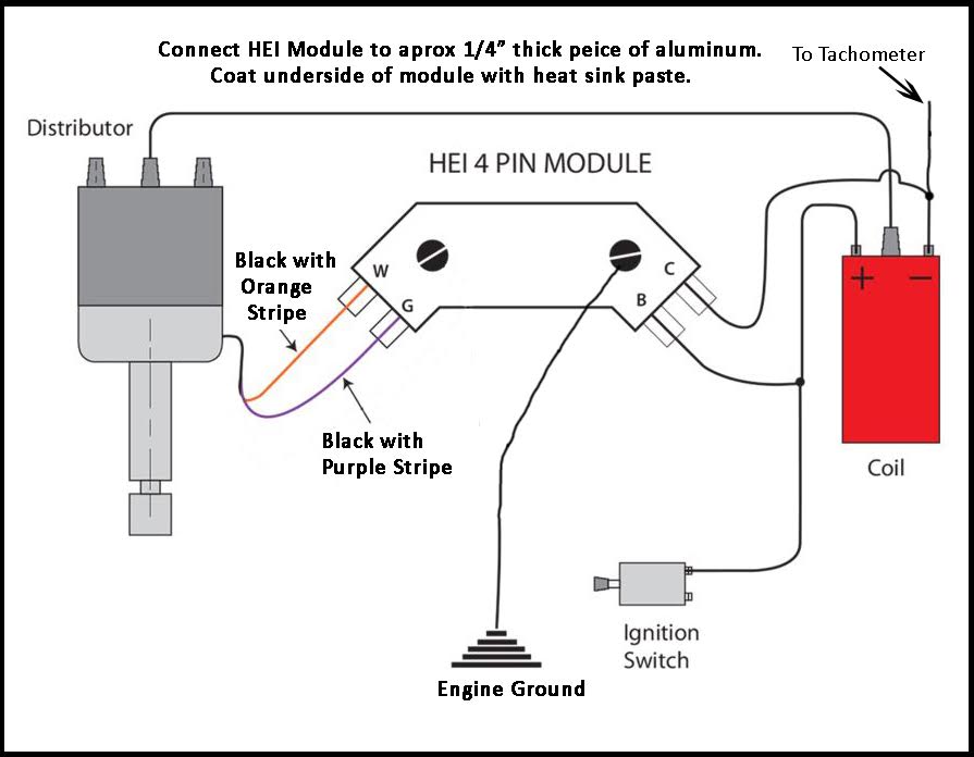
- HEI Module: Generates the electrical pulses that trigger spark production in the ignition coil.
- Centrifugal Advance: Adjusts ignition timing based on engine speed.
- Vacuum Advance: Adjusts ignition timing based on engine load.
- Pick-up Coil: Senses the position of the distributor’s rotating shaft, triggering spark at the appropriate moment.
- Ignition Control Module (ICM): Controls the HEI module and provides power to the ignition coil (in some HEI systems).
- Wiring Harness: Connects the various components of the HEI system.
- Spark Plugs: Ignite the air-fuel mixture within the engine’s cylinders.
These aspects collectively ensure proper spark generation, distribution, and timing, ultimately contributing to optimal engine performance and efficiency. A thorough understanding of their functions and interactions is essential for effective HEI system maintenance and repair.
Distributor Cap
Within the context of “2 Wire HEI Distributor Wiring Diagram”, the distributor cap plays a pivotal role in the high voltage distribution network. The distributor cap sits atop the distributor body and comprises several crucial components working in conjunction to ensure efficient spark delivery.
- Electrical Terminals: Conductive terminals within the distributor cap establish electrical connections with the spark plug wires. These terminals are specifically designed to withstand high voltage and maintain consistent contact.
- Center Contact: The center contact, also known as the rotor contact, is a pivotal component of the distributor cap. It receives high voltage from the ignition coil and distributes it to the appropriate electrical terminals, ensuring proper spark delivery to each spark plug.
- Insulator: The distributor cap serves as an insulator, preventing high voltage from arcing or leaking between terminals. This insulation ensures that electrical energy is directed exclusively through the intended paths.
- Ventilation System: A ventilation system incorporated into the distributor cap helps dissipate heat, moisture, and any potential contaminants that could compromise electrical performance or lead to premature cap failure.
The distributor cap’s effective functioning is essential for the overall performance and reliability of the HEI ignition system. Regular inspection, maintenance, and replacement of the distributor cap, if necessary, contribute to optimal engine operation and prevent potential issues or breakdowns related to high voltage distribution.
Rotor
Within the context of “2 Wire HEI Distributor Wiring Diagram”, the rotor plays a vital role in ensuring that high voltage is distributed and directed to the appropriate spark plug terminals. It is a critical component that facilitates the transfer of electrical energy from the distributor cap to the spark plugs, promoting efficient engine operation and performance.
- Contact Points: The rotor comprises conductive contact points that establish connections with the distributor cap’s electrical terminals. These contact points are designed to withstand high voltage and maintain consistent electrical connections.
- Insulation: The rotor incorporates insulation to prevent electrical arcing or leakage between the contact points and the distributor shaft. This insulation ensures that electrical energy is directed exclusively through the intended paths.
- Centrifugal Advance Mechanism: In some HEI distributors, the rotor is coupled with a centrifugal advance mechanism. This mechanism adjusts the timing of spark delivery based on engine speed, optimizing engine performance across different operating conditions.
- Compatibility: Rotors are designed to be compatible with specific distributor caps and ignition systems. Using the correct rotor for the intended application is crucial to ensure proper fit, electrical connectivity, and overall system performance.
The rotor’s effective functioning is essential for the optimal performance of the “2 Wire HEI Distributor Wiring Diagram”. Regular inspection and maintenance of the rotor, including cleaning any corrosion or carbon buildup on its contact points, contribute to the overall reliability and efficiency of the HEI ignition system.
Ignition Coil
Within the context of “2 Wire HEI Distributor Wiring Diagram”, the ignition coil assumes a critical role in generating the high voltage required for spark production, which is essential for igniting the air-fuel mixture within the engine’s cylinders. The ignition coil’s functioning is intricately linked to the overall operation and effectiveness of the “2 Wire HEI Distributor Wiring Diagram”.
In essence, the ignition coil serves as a step-up transformer, converting the relatively low voltage provided by the battery into the thousands of volts necessary to create a spark across the spark plug gap. This high voltage is then distributed to the appropriate spark plugs by the distributor, ensuring synchronized ignition and optimal engine performance.
Real-life examples of the ignition coil’s critical role within the “2 Wire HEI Distributor Wiring Diagram” can be observed in various automotive applications. In older vehicles, the ignition coil was typically mounted externally on the engine or firewall. In modern vehicles, however, the ignition coil is often incorporated into the distributor assembly, forming a compact and integrated unit.
Understanding the relationship between the ignition coil and the “2 Wire HEI Distributor Wiring Diagram” is crucial for effective troubleshooting and maintenance of the ignition system. A faulty or malfunctioning ignition coil can lead to weak or no spark, resulting in engine misfiring or failure to start. Regular inspection and testing of the ignition coil, along with prompt replacement if necessary, are essential to maintain optimal engine performance and reliability.
HEI Module
Within the scope of “2 Wire Hei Distributor Wiring Diagram”, the HEI module stands as a pivotal component, orchestrating the precise generation of electrical pulses that initiate spark production within the ignition coil. This intricate process underpins the smooth functioning of the engine, ensuring optimal combustion and maximizing engine performance.
- Pulse Generation: The HEI module’s primary function lies in generating electrical pulses of specific duration and timing. These pulses are transmitted to the ignition coil, triggering the buildup of high voltage necessary for spark creation.
- Timing Control: The HEI module precisely controls the timing of spark delivery, ensuring that the spark occurs at the optimal moment during the engine’s combustion cycle. This timing is crucial for maximizing engine efficiency and minimizing emissions.
- Dwell Period: The HEI module regulates the dwell period, which refers to the duration of current flow through the ignition coil. This dwell period directly influences the intensity and duration of the spark produced.
- Electronic Ignition: The HEI module eliminates the need for traditional mechanical points or breaker plates, employing electronic circuitry to generate the ignition pulses. This electronic approach enhances reliability, precision, and overall system durability.
In conclusion, the HEI module’s role in generating electrical pulses for spark production is fundamental to the effectiveness of “2 Wire Hei Distributor Wiring Diagram”. Its precise pulse generation, timing control, and electronic ignition capabilities contribute to optimal engine performance, reliability, and efficiency.
Centrifugal Advance
Within the context of the “2 Wire HEI Distributor Wiring Diagram”, the centrifugal advance mechanism plays a crucial role in optimizing engine performance across varying operating conditions. Its primary function is to adjust the timing of spark delivery based on engine speed, ensuring that the spark occurs at the optimal moment during the combustion cycle.
The centrifugal advance mechanism typically comprises weights and springs housed within the distributor. As engine speed increases, the weights move outward due to centrifugal force, causing the distributor shaft to rotate slightly. This rotation advances the timing of spark delivery, ensuring that the spark occurs earlier in the compression stroke. This advanced timing is necessary at higher engine speeds to compensate for the increased time required for the flame to propagate within the combustion chamber.
Conversely, as engine speed decreases, the weights move inward, retarding the timing of spark delivery. This retarded timing is necessary at lower engine speeds to prevent premature ignition and potential engine damage.
The centrifugal advance mechanism is an integral component of the “2 Wire HEI Distributor Wiring Diagram”, contributing to efficient engine operation and maximizing power output. Its ability to adjust ignition timing based on engine speed ensures optimal combustion, reduces emissions, and enhances overall engine performance.
In summary, the centrifugal advance mechanism’s relationship with the “2 Wire HEI Distributor Wiring Diagram” is critical for achieving optimal engine performance across varying operating conditions. Its ability to adjust ignition timing based on engine speed ensures efficient combustion, reduces emissions, and maximizes power output.
Vacuum Advance
Within the context of the “2 Wire HEI Distributor Wiring Diagram”, the vacuum advance mechanism plays a crucial role in optimizing engine performance under varying load conditions. Its primary function is to adjust the timing of spark delivery based on engine load, ensuring that the spark occurs at the optimal moment during the combustion cycle and maximizing engine efficiency.
The vacuum advance mechanism is connected to the engine’s intake manifold, which experiences a vacuum as the engine draws in air. As engine load increases, the vacuum in the intake manifold decreases. The vacuum advance mechanism responds to this change in vacuum by moving a diaphragm, which in turn adjusts the position of the distributor shaft. This movement advances the timing of spark delivery, ensuring that the spark occurs earlier in the compression stroke under higher load conditions.
The benefits of vacuum advance include improved engine performance, reduced emissions, and increased fuel economy. By advancing the timing of spark delivery under higher load conditions, the vacuum advance mechanism allows for more complete combustion of the air-fuel mixture, resulting in increased power output and reduced emissions. Additionally, the more efficient combustion process reduces fuel consumption, leading to improved fuel economy.
In summary, the vacuum advance mechanism is an essential component of the “2 Wire HEI Distributor Wiring Diagram”, contributing to optimal engine performance, reduced emissions, and improved fuel economy. Its ability to adjust ignition timing based on engine load ensures efficient combustion under varying operating conditions.
Pick-up Coil
Within the comprehensive landscape of “2 Wire HEI Distributor Wiring Diagram”, the pick-up coil stands as a pivotal component, orchestrating the precise delivery of ignition spark. Its intricate functioning underpins the optimal performance, efficiency, and reliability of the engine.
- Synchronous Ignition: The pick-up coil’s primary role lies in detecting the position of the distributor’s rotating shaft. This information is crucial for synchronizing the ignition spark with the piston’s movement within the combustion chamber. By triggering the spark at the optimal moment, the pick-up coil ensures efficient fuel combustion and maximizes engine performance.
- Magnetic Induction: The pick-up coil operates on the principle of magnetic induction. As the distributor’s rotating shaft spins, it carries a reluctor wheel with notches or slots. The pick-up coil, positioned near the reluctor wheel, senses the changes in magnetic field caused by the passing notches or slots. These changes induce electrical pulses within the pick-up coil, providing the necessary signal to trigger the ignition.
- Electronic Ignition: The pick-up coil plays a central role in electronic ignition systems, eliminating the need for traditional mechanical points or breaker plates. Its electronic signal is processed by the HEI module, which then generates the high-voltage pulses required to ignite the spark plugs.
- Reliability and Durability: Compared to mechanical ignition systems, the pick-up coil offers enhanced reliability and durability. It is less prone to wear and tear, ensuring consistent and precise spark timing over an extended lifespan.
In conclusion, the pick-up coil is an essential element within the “2 Wire HEI Distributor Wiring Diagram”, responsible for sensing the distributor’s shaft position and triggering spark at the optimal moment. Its contributions to synchronous ignition, magnetic induction, electronic ignition, and overall reliability make it a critical component for the efficient and dependable operation of internal combustion engines.
Ignition Control Module (ICM)
Within the intricate web of “2 Wire Hei Distributor Wiring Diagram”, the Ignition Control Module (ICM) emerges as a pivotal component, orchestrating the seamless functioning of the ignition system. Its multifaceted role encompasses controlling the HEI module and, in certain HEI systems, providing power to the ignition coil. This comprehensive analysis delves into the key aspects of the ICM, illuminating its significance within the broader context of “2 Wire Hei Distributor Wiring Diagram”.
-
ICM and HEI Module Control:
The ICM stands as the maestro of the HEI module, meticulously managing its operations. It precisely regulates the timing and duration of ignition pulses generated by the HEI module, ensuring optimal spark delivery to the spark plugs.
-
Power Supply to Ignition Coil:
In certain HEI systems, the ICM assumes the additional responsibility of supplying power to the ignition coil. This critical function ensures that the coil receives the necessary voltage to generate the high-voltage pulses required for spark creation.
-
Compact Integration:
The ICM often resides within the distributor housing, forming a compact and efficient assembly. This integrated design simplifies installation, reduces wiring complexity, and enhances overall system reliability.
-
Electronic Ignition:
The ICM’s electronic circuitry eliminates the need for traditional mechanical points or breaker plates, resulting in a more precise and dependable ignition system. This electronic approach contributes to improved engine performance, reduced emissions, and enhanced fuel economy.
In conclusion, the Ignition Control Module plays a multifaceted role within the “2 Wire Hei Distributor Wiring Diagram”. Its precise control over the HEI module and, in some systems, its ability to power the ignition coil, make it an indispensable component for the efficient and reliable operation of the ignition system. Understanding the ICM’s functions and interactions is crucial for effective troubleshooting and maintenance of HEI systems, ensuring optimal engine performance and longevity.
Wiring Harness
Within the intricate tapestry of “2 Wire Hei Distributor Wiring Diagram”, the wiring harness serves as the vital conduit, interconnecting the diverse components of the High Energy Ignition (HEI) system. This intricate network of wires and connectors ensures the seamless flow of electrical signals and power, orchestrating the precise functioning of each component and enabling optimal engine performance. Embarking on a detailed exploration of this crucial element, we unravel its multifaceted role and delve into its specific components and implications.
-
Electrical Signal Transmission:
The wiring harness facilitates the transmission of intricate electrical signals between the HEI module, ignition coil, distributor cap, and spark plugs. These signals precisely control the timing and duration of spark delivery, ensuring synchronized ignition and optimal combustion.
-
Power Distribution:
In addition to signal transmission, the wiring harness also serves as the lifeline for power distribution. It supplies electrical current from the battery to the HEI module, ignition coil, and other components, enabling them to fulfill their respective functions.
-
Reliable Connections:
The wiring harness is meticulously designed to establish secure and reliable electrical connections between components. It utilizes high-quality connectors and insulated wires to prevent short circuits, voltage drops, and other electrical gremlins that could compromise system performance.
-
Harness Design and Installation:
The wiring harness is meticulously engineered to accommodate the specific layout and requirements of the HEI system. Its design ensures proper routing, protection from heat and abrasion, and ease of installation or replacement, facilitating efficient maintenance and repairs.
In conclusion, the wiring harness plays an indispensable role within the “2 Wire Hei Distributor Wiring Diagram”, forming the backbone of electrical communication and power distribution. Its intricate design and reliable connections ensure the seamless functioning of the HEI system, contributing to optimal engine performance, reduced emissions, and enhanced fuel economy. Understanding the components and implications of the wiring harness empowers technicians and enthusiasts to diagnose and resolve electrical issues, ensuring the longevity and reliability of their HEI-equipped vehicles.
Spark Plugs
Within the intricate tapestry of “2 Wire HEI Distributor Wiring Diagram”, spark plugs emerge as pivotal components, responsible for igniting the air-fuel mixture within the engine’s cylinders. Their precise operation forms the cornerstone of efficient combustion, optimal engine performance, and reduced emissions. Delving into this crucial aspect, we explore various facets of spark plugs and their profound implications within the broader context of “2 Wire HEI Distributor Wiring Diagram”.
-
Electrode Design:
Spark plugs feature meticulously engineered electrodes that create the electrical spark necessary for ignition. The shape, size, and material composition of these electrodes directly impact the quality and intensity of the spark, influencing combustion efficiency and engine performance.
-
Insulation and Heat Resistance:
Spark plugs must withstand extreme temperatures and electrical voltages within the combustion chamber. Their insulation and heat-resistant properties ensure reliable operation under these demanding conditions, preventing electrical leakage and premature failure.
-
Gap Setting:
The gap between the spark plug’s electrodes plays a critical role in ignition timing and spark intensity. Proper gap setting is crucial for optimal engine performance, preventing misfires and ensuring efficient combustion.
-
Compatibility and Applications:
Spark plugs are designed to meet the specific requirements of different engines and applications. Factors such as thread size, reach, and heat range must be carefully considered to ensure proper fitment and optimal performance in various vehicle models and operating conditions.
In conclusion, spark plugs are indispensable components within “2 Wire HEI Distributor Wiring Diagram”, performing the critical task of igniting the air-fuel mixture and initiating combustion within the engine’s cylinders. Their design, materials, and precise functioning directly influence engine performance, efficiency, and emissions. By understanding the various facets of spark plugs, technicians and enthusiasts can optimize ignition systems, troubleshoot issues, and ensure the longevity of their vehicles.


Related Posts


