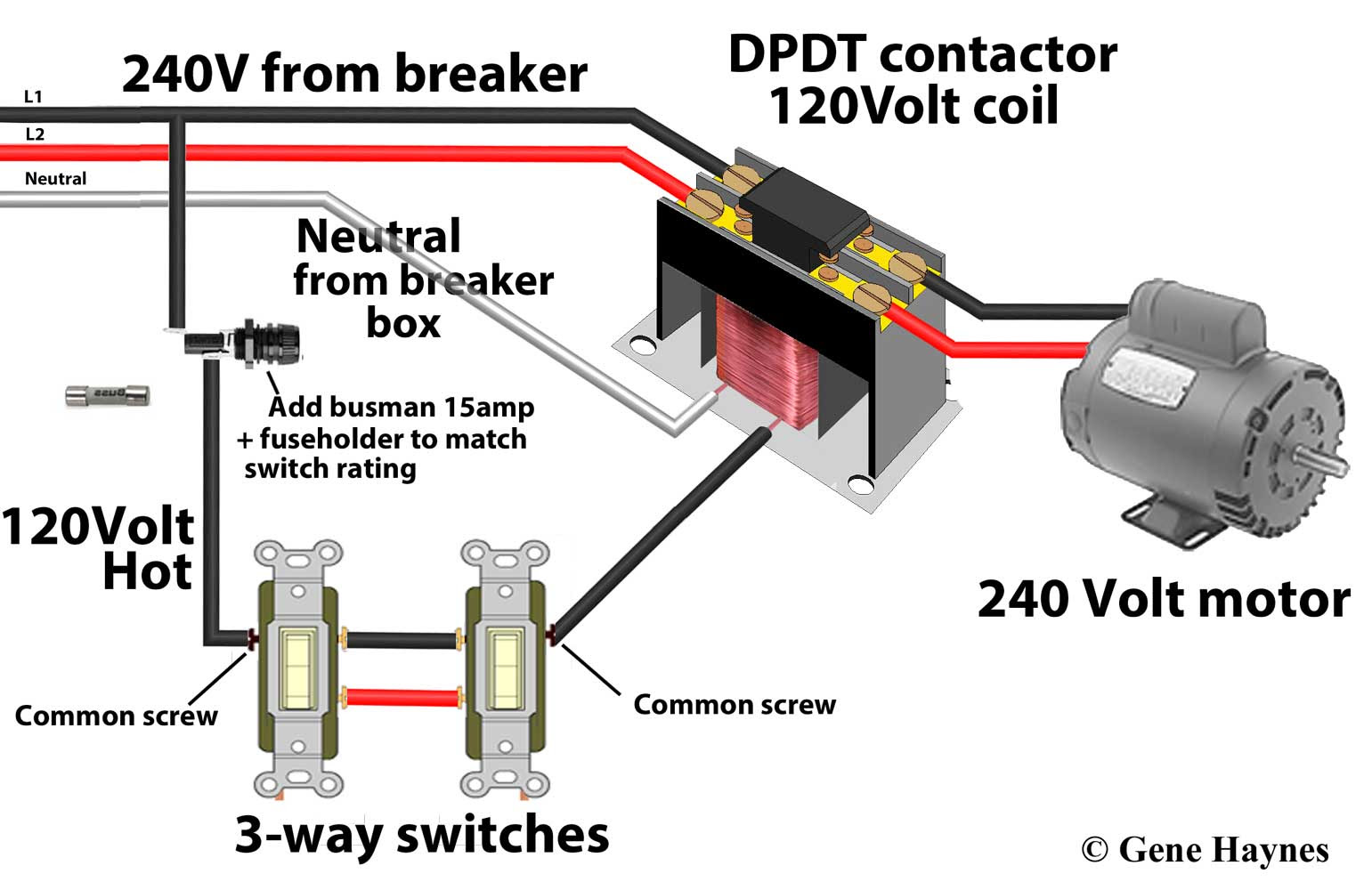
A 120v relay wiring diagram is a schematic representation of the electrical connections required to operate a 120-volt relay. It illustrates the flow of current through the relay’s coil, contacts, and terminals, guiding the proper installation and operation of the relay within an electrical system. For instance, in a home automation setup, a 120v relay can be used to control the on/off function of a light fixture.
Understanding relay wiring diagrams is crucial for ensuring the correct functioning of electrical circuits. It aids in troubleshooting issues, preventing electrical hazards, and optimizing the performance of electrical systems.
The advent of solid-state relays marked a key historical development in relay technology. These relays offer advantages such as increased reliability, faster switching times, and extended lifespan compared to traditional electromechanical relays.
A 120v relay wiring diagram is a crucial aspect of electrical engineering, providing a visual representation of the connections required for a 120-volt relay to function properly within an electrical system.
- Components: A wiring diagram illustrates the relay’s coil, contacts, terminals, and their connections.
- Connection types: It specifies whether the relay connections are normally open (NO) or normally closed (NC).
- Voltage compatibility: The diagram ensures that the relay is compatible with the 120-volt power supply.
- Circuit protection: It incorporates elements like fuses or circuit breakers to protect the relay and the connected circuit.
- Load capacity: The wiring diagram indicates the maximum load that the relay can handle.
- Switching mechanism: It details the type of switching mechanism used by the relay, such as electromechanical or solid-state.
- Control logic: The diagram may include information about the control logic used to operate the relay.
- Safety considerations: It highlights safety measures, such as proper grounding and insulation, to prevent electrical hazards.
Understanding these key aspects is essential for designing, installing, and maintaining electrical systems that incorporate 120v relays. Proper wiring ensures efficient and reliable operation, prevents malfunctions, and enhances the safety of the electrical system.
Components
Within a 120v relay wiring diagram, the components play a critical role in establishing the necessary electrical connections and defining the relay’s behavior. The coil, contacts, terminals, and their interconnections determine the relay’s functionality and its ability to control electrical circuits.
The coil is an electromagnetic component that, when energized, creates a magnetic field. This magnetic field actuates the relay’s contacts, causing them to open or close. The contacts are the switching elements of the relay, responsible for controlling the flow of current in the connected circuit.
Terminals provide the electrical connection points for the coil, contacts, and external circuitry. Proper wiring of the terminals is crucial to ensure that the relay operates as intended. A clear understanding of these components and their connections is essential for designing, installing, and troubleshooting 120v relay circuits.
In practical applications, 120v relay wiring diagrams are used in various electrical systems, including home appliances, industrial control panels, and automotive electronics. By understanding the components and their interconnections, technicians can effectively troubleshoot and repair relay-based circuits, ensuring the proper functioning of the electrical system.
Connection types
In the context of 120v relay wiring diagrams, connection types refer to the default state of the relay’s contacts when the coil is not energized. Understanding these connection types is crucial for designing and installing relay circuits as they determine the initial state of the circuit before the relay is activated.
-
Normally Open (NO):
In a NO connection, the relay contacts are open by default when the coil is not energized. When the coil is energized, the contacts close, allowing current to flow through the circuit. -
Normally Closed (NC):
In a NC connection, the relay contacts are closed by default when the coil is not energized. When the coil is energized, the contacts open, interrupting the flow of current through the circuit.
The choice between NO and NC connections depends on the desired behavior of the circuit. For instance, in a lighting control circuit, a NO connection ensures that the light is initially off when the relay is not energized, while a NC connection ensures that the light is initially on.
Understanding connection types is essential for proper relay circuit design, troubleshooting, and maintenance. Incorrectly wired connections can lead to malfunctioning circuits and potential safety hazards. Therefore, careful consideration of the required connection type is crucial to ensure the intended functionality and safety of the electrical system.
Voltage compatibility
Voltage compatibility is a fundamental aspect of 120v relay wiring diagrams, ensuring the safe and effective operation of the relay within an electrical system. The diagram plays a critical role in verifying that the relay is suitable for use with a 120-volt power supply, preventing potential damage or malfunctions.
- Coil Voltage: The wiring diagram specifies the voltage required to energize the relay’s coil. In the case of a 120v relay, the coil must be compatible with a 120-volt power supply to create the necessary magnetic field for contact actuation.
- Contact Rating: The diagram indicates the voltage rating of the relay’s contacts. This rating ensures that the contacts can safely handle the voltage present in the circuit. Exceeding the contact rating can lead to arcing, contact welding, and potential electrical hazards.
- Power Source: The wiring diagram should include details about the power source that will supply the 120 volts to the relay. This information guides the selection of appropriate wiring and circuit protection measures to ensure compatibility with the power source.
- Circuit Protection: The diagram incorporates circuit protection elements, such as fuses or circuit breakers, to safeguard the relay and the connected circuit from overcurrent conditions. These protective devices ensure that the relay operates within its voltage limits, preventing damage due to voltage spikes or surges.
Understanding voltage compatibility is essential for selecting the correct relay and designing a safe and functional electrical system. By adhering to the specifications outlined in the 120v relay wiring diagram, electrical professionals can prevent costly mistakes, ensure reliable operation, and maintain the integrity of the electrical system.
Circuit protection
Within the context of 120v relay wiring diagrams, circuit protection plays a pivotal role in ensuring the safety and reliability of the electrical system. The diagram incorporates elements like fuses or circuit breakers to safeguard the relay and the connected circuit from potential electrical faults, overloads, and short circuits.
- Fuses: Fuses are sacrificial devices that interrupt the circuit when the current exceeds a predetermined safe level. In a 120v relay wiring diagram, fuses are typically placed in series with the relay coil to protect it from overcurrent damage.
- Circuit Breakers: Circuit breakers are reusable protective devices that trip when the current exceeds a certain threshold. They can be manually reset once the fault is cleared, making them a more convenient option for repeated protection.
- Overcurrent Protection: Circuit protection elements prevent excessive current from flowing through the relay and the connected circuit, which can cause overheating, damage to components, and even fire hazards. By limiting the current to safe levels, circuit protection ensures the longevity and reliability of the electrical system.
- Ground Fault Protection: In certain applications, ground fault circuit interrupters (GFCIs) may be incorporated into the wiring diagram to protect against electrical shocks. GFCIs detect imbalances between the current flowing in the live and neutral conductors, indicating a potential ground fault, and quickly interrupt the circuit to prevent electrocution.
Understanding and implementing proper circuit protection measures as outlined in the 120v relay wiring diagram is crucial for the safe and efficient operation of the electrical system. By incorporating the appropriate protective elements, electrical professionals can minimize the risk of electrical accidents, safeguard equipment, and ensure the integrity of the electrical circuit.
Load capacity
In the context of 120v relay wiring diagrams, load capacity holds significant importance as it determines the maximum electrical load that the relay can safely switch or control. Understanding and adhering to the load capacity specified in the wiring diagram is crucial for ensuring the safe and reliable operation of the electrical system.
- Relay Contacts: The wiring diagram specifies the current and voltage ratings of the relay’s contacts. These ratings indicate the maximum load that the contacts can safely handle without overheating or arcing. Exceeding the contact ratings can lead to premature contact failure and potential electrical hazards.
- Coil Power Consumption: The wiring diagram provides information about the coil’s power consumption, which is the amount of power required to energize the relay. This information helps in selecting an appropriate power supply that can adequately power the relay without overloading the circuit.
- Circuit Breaker or Fuse Selection: The load capacity of the relay influences the selection of circuit breakers or fuses used in the circuit. The protective devices should be rated to handle the maximum load current drawn by the relay and the connected load.
- Wiring Gauge: The wiring diagram specifies the appropriate wire gauge for connecting the relay to the power source and the load. The wire gauge must be able to safely carry the maximum load current without overheating or causing excessive voltage drop.
Understanding and adhering to the load capacity specified in the 120v relay wiring diagram is paramount for the safe and efficient operation of the electrical system. By considering the relay’s contact ratings, coil power consumption, and implications on circuit protection and wiring, electrical professionals can design and install reliable and safe electrical circuits that meet the intended load requirements.
Switching mechanism
Within the context of 120v relay wiring diagrams, the switching mechanism plays a critical role in determining the relay’s operation and application. The wiring diagram specifies the type of switching mechanism employed by the relay, which can be either electromechanical or solid-state.
Electromechanical Relays: In electromechanical relays, the switching mechanism involves physical contacts that open or close to control the flow of current. The coil, when energized, creates a magnetic field that actuates the contacts, either opening or closing them. Electromechanical relays are characterized by their durability, high current-carrying capacity, and relatively low cost.
Solid-State Relays: Solid-state relays (SSRs) utilize electronic components, such as transistors or thyristors, to perform the switching function. They do not have physical contacts, eliminating the arcing and wear associated with electromechanical relays. SSRs offer advantages like faster switching speeds, longer lifespan, and immunity to electrical noise.
Selection Considerations: The choice between electromechanical and solid-state relays depends on factors such as the required switching frequency, current and voltage ratings, environmental conditions, and cost. Electromechanical relays are typically preferred for applications involving high currents and infrequent switching, while SSRs are more suitable for high-speed switching, low-level signals, and environments sensitive to electrical noise.
Understanding the switching mechanism is crucial for selecting the appropriate relay for a specific application and designing a reliable 120v relay wiring diagram. The specified switching mechanism dictates the relay’s characteristics, performance, and compatibility with the intended circuit.
Control logic
Control logic plays a critical role in designing and implementing 120v relay wiring diagrams. It refers to the circuitry or programming that governs the operation and behavior of the relay within an electrical system. Understanding and incorporating control logic into the wiring diagram is essential for ensuring the intended functionality and safe operation of the relay.
- Logic Gates: Logic gates are fundamental building blocks of control logic. They perform basic logical operations, such as AND, OR, and NOT, to process input signals and generate an output that controls the relay’s state.
- Timers and Counters: Timers introduce time delays into the control logic, enabling precise timing sequences. Counters keep track of events or pulses, allowing the relay to respond to specific patterns or counts.
- Programmable Logic Controllers (PLCs): PLCs are small computers that can be programmed to implement complex control logic. They offer flexibility and expandability, making them suitable for controlling multiple relays and handling various input/output signals.
- Microcontrollers: Microcontrollers are single-chip computers that combine processing, memory, and input/output capabilities. They provide a compact and cost-effective solution for implementing control logic in embedded systems.
Incorporating control logic into 120v relay wiring diagrams allows for sophisticated control over the relay’s operation. It enables the relay to respond to specific input conditions, perform timed actions, count events, or execute more complex control algorithms. Understanding and designing control logic is essential for creating reliable and efficient relay-based systems.
Safety considerations
Within the context of 120v relay wiring diagrams, safety considerations are paramount to ensure the protection of individuals and equipment from electrical hazards. These diagrams emphasize proper grounding and insulation as critical measures to prevent electrical shock, fires, and other dangerous situations.
Grounding: Proper grounding provides a low-resistance path for fault currents to flow back to the electrical source. In a 120v relay wiring diagram, the relay’s metal enclosure is typically connected to the grounding conductor, which is connected to the earth ground. This ensures that any stray currents or fault currents are safely dissipated, reducing the risk of electrical shock.
Insulation: Adequate insulation of electrical components prevents current leakage and short circuits. In a 120v relay wiring diagram, the relay coil and contacts are insulated to prevent accidental contact with other components or the enclosure. Proper insulation also safeguards against electrical breakdown and arcing, which can lead to fires or equipment damage.
Real-Life Examples: In a home electrical system, a 120v relay may be used to control a lighting circuit. The relay wiring diagram should incorporate proper grounding and insulation to protect against potential hazards. If the relay enclosure is not properly grounded, a fault current could flow through the enclosure and pose a shock hazard. Similarly, inadequate insulation could lead to arcing or short circuits, potentially causing a fire.
Understanding and adhering to safety considerations in 120v relay wiring diagrams is crucial for the safe installation, operation, and maintenance of electrical systems. By implementing proper grounding and insulation measures, electrical professionals can minimize the risk of electrical accidents, protect equipment, and ensure the reliability of the electrical system.


![[DIAGRAM] Electrical Wiring Diagrams 120v Junction](https://i0.wp.com/3.bp.blogspot.com/_NFgLJr6_3jk/TRGVND3L5rI/AAAAAAAAAC4/zq4N1lNP-ik/s1600/120v%252Bheater%252Bwiring.png?w=665&ssl=1)


Related Posts


