A 120v Plug Wiring Diagram is a schematic representation of how to wire a 120-volt electrical outlet. It provides detailed guidance, including the correct wire colors, connection points, and grounding requirements. By following the diagram, electricians can safely install or repair electrical outlets, ensuring they comply with electrical codes and regulations.
Properly wired outlets are crucial for providing power to various household appliances and devices. They help minimize electrical hazards such as short circuits and shocks. Understanding 120v Plug Wiring Diagrams empowers electricians and DIY enthusiasts to confidently work on electrical projects.
A significant historical development in outlet wiring is the introduction of polarized plugs and outlets. Polarized plugs have one wider blade than the other, ensuring the correct orientation when inserted. This design enhances safety by preventing accidental contact with live wires.
Understanding the essential aspects of “120v Plug Wiring Diagram” is pivotal for safe and efficient electrical installations. Here’s an exploration of ten key aspects:
- Circuit Protection: Diagrams guide the correct connection of circuit breakers or fuses, safeguarding against overcurrent.
- Wire Gauge: Diagrams specify the appropriate wire thickness, ensuring adequate current flow and preventing overheating.
- Grounding: Diagrams ensure proper grounding of the outlet, providing a safe path for fault currents.
- Polarity: Diagrams indicate the correct orientation of the plug blades, preventing accidental contact with live wires.
- Outlet Box: Diagrams detail the compatible outlet box size and mounting requirements for a secure installation.
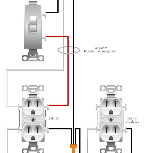
- Receptacle Type: Diagrams specify the type of outlet receptacle, such as duplex or GFCI, based on the intended use.
- Faceplate: Diagrams include the faceplate design and material, ensuring a proper fit and finish.
- Voltage and Current Ratings: Diagrams indicate the outlet’s voltage and current capacity, matching the requirements of the connected devices.
- Electrical Code Compliance: Diagrams adhere to electrical codes and standards, guaranteeing safety and compliance.
- Tools and Materials: Diagrams outline the necessary tools and materials for installation, ensuring proper execution.
These aspects are interconnected, ensuring the safe and reliable operation of 120v electrical outlets. By understanding and following these aspects, electricians and DIY enthusiasts can confidently tackle electrical projects, ensuring code compliance and minimizing electrical hazards.
Circuit Protection
Circuit protection is a critical aspect of 120v Plug Wiring Diagrams. By providing guidance on the correct connection of circuit breakers or fuses, these diagrams ensure that electrical circuits are protected against overcurrent, reducing the risk of electrical fires and other hazards.
- Circuit Breakers: Circuit breakers are reusable devices that automatically trip when the current exceeds a predetermined level. They are commonly used in residential and commercial electrical systems to protect circuits from overloads and short circuits.
- Fuses: Fuses are single-use devices that blow (break the circuit) when the current exceeds a specified level. They are often used in industrial and automotive applications, as well as in some older residential electrical systems.
- Correct Connection: Circuit breakers and fuses must be correctly connected to the electrical circuit in order to provide effective protection. Wiring diagrams specify the proper connection points for these devices, ensuring that they are installed in series with the circuit and that the correct wire gauge is used.
- Overcurrent Protection: Overcurrent occurs when the current flowing through a circuit exceeds the rated capacity of the circuit or its components. Circuit breakers and fuses are designed to interrupt the circuit when overcurrent occurs, preventing damage to the circuit, appliances, and property.
By adhering to the guidance provided in 120v Plug Wiring Diagrams, electricians and DIY enthusiasts can ensure that electrical circuits are properly protected against overcurrent, minimizing the risk of electrical hazards and ensuring the safe operation of electrical outlets.
Wire Gauge
In the context of “120v Plug Wiring Diagrams,” specifying the appropriate wire gauge is crucial for the safe and efficient operation of electrical outlets. Wiring diagrams provide clear guidance on the correct wire thickness to use, ensuring that electrical circuits can handle the intended current flow without overheating or causing electrical hazards.
- Current Carrying Capacity: The wire gauge, typically measured in American Wire Gauge (AWG), determines the amount of current that a wire can safely carry. Wiring diagrams specify the appropriate wire gauge based on the expected current draw of the connected devices, ensuring that the wire can handle the load without overheating.
- Voltage Drop: Using the correct wire gauge minimizes voltage drop, which is the reduction in voltage that occurs as electricity flows through a wire. Excessive voltage drop can lead to inefficient operation of appliances and devices. Wiring diagrams account for voltage drop and specify the appropriate wire gauge to maintain adequate voltage levels.
- Heat Dissipation: Thicker wires have a larger surface area, allowing them to dissipate heat more effectively. Wiring diagrams ensure that the specified wire gauge is thick enough to handle the current flow without overheating, preventing damage to the wire insulation and potential electrical fires.
- Code Compliance: Electrical codes and standards specify the minimum wire gauge that can be used for different applications. Wiring diagrams adhere to these codes, ensuring that the installed wiring meets safety requirements and complies with local regulations.
By specifying the appropriate wire gauge, 120v Plug Wiring Diagrams empower electricians and DIY enthusiasts to install and maintain electrical outlets safely and efficiently. Adhering to these guidelines helps prevent electrical hazards, ensures optimal performance of electrical devices, and maintains compliance with electrical codes.
Grounding
Within the context of “120v Plug Wiring Diagrams,” grounding plays a crucial role in ensuring the safe operation of electrical outlets. Grounding provides a low-resistance path for fault currents to flow, protecting individuals from electrical shocks and preventing damage to equipment.
- Grounding Wire: Wiring diagrams specify the proper connection of a grounding wire, which is typically bare copper or green-insulated. The grounding wire connects the outlet to the electrical panel’s grounding system, providing a direct path for fault currents to flow to the earth.
- Grounding Terminal: Outlets have a dedicated grounding terminal, which is typically a green screw or terminal. Wiring diagrams indicate the correct connection point for the grounding wire, ensuring a secure and reliable connection to the outlet’s grounding system.
- Ground Fault Circuit Interrupter (GFCI): GFCIs are specialized outlets that monitor the balance of current flowing through the hot and neutral wires. If an imbalance occurs, indicating a fault condition, the GFCI quickly interrupts the circuit, preventing electrical shocks.
- Electrical Code Compliance: Wiring diagrams adhere to electrical codes and standards that mandate the proper grounding of electrical outlets. By following these guidelines, electricians and DIY enthusiasts ensure that their installations meet safety requirements and minimize the risk of electrical hazards.
Proper grounding is essential for the safe operation of 120v electrical outlets. By providing detailed guidance on grounding wire connections, grounding terminals, and GFCI protection, 120v Plug Wiring Diagrams empower individuals to install and maintain electrical outlets that comply with electrical codes and safeguard against electrical shocks and equipment damage.
Polarity
Within the context of “120v Plug Wiring Diagrams,” polarity plays a critical role in ensuring the safe and reliable operation of electrical outlets. Polarity refers to the correct orientation of the plug blades, which are designed to prevent accidental contact with live wires and minimize the risk of electrical shocks.
A crucial component of 120v Plug Wiring Diagrams, polarity is achieved through the use of polarized plugs and outlets. Polarized plugs have one wider blade and one narrower blade, ensuring that the plug can only be inserted into the outlet in one specific orientation. This design ensures that the live wire is always connected to the correct terminal on the outlet, preventing contact with the neutral wire or ground terminal.
The importance of polarity is evident in real-life examples. Improperly wired outlets, where polarity is not maintained, can pose a significant electrical hazard. If a non-polarized plug is inserted into a polarized outlet in the incorrect orientation, the live wire may come into contact with the neutral wire or ground terminal, creating a short circuit and potentially causing an electrical fire or shock.
Understanding polarity and following the guidance provided in 120v Plug Wiring Diagrams is essential for safe electrical installations and maintenance. By ensuring the correct orientation of plug blades, electricians and DIY enthusiasts can minimize the risk of electrical accidents and ensure the proper functioning of electrical outlets.
In conclusion, polarity is a critical aspect of 120v Plug Wiring Diagrams, guiding the correct orientation of plug blades to prevent accidental contact with live wires. Maintaining polarity is essential for electrical safety and compliance with electrical codes, ensuring the reliable and hazard-free operation of electrical outlets.
Outlet Box
In the context of “120v Plug Wiring Diagrams,” understanding the intricacies of outlet boxes is crucial for safe and durable electrical installations. Outlet boxes serve as the housing and support structure for electrical outlets, providing a secure enclosure and ensuring proper alignment and functionality.
- Box Type and Size: Wiring diagrams specify the compatible outlet box type and size based on the intended application. Common types include single-gang, double-gang, and old work boxes, each designed to accommodate a specific number of outlets and depths of walls.
- Mounting Requirements: Diagrams provide detailed instructions on mounting the outlet box securely within the wall. This includes specifying the appropriate fasteners, such as screws or nails, and indicating the correct spacing and alignment to ensure a flush and stable installation.
- Knockouts and Cable Entry: Diagrams indicate the location of knockouts, which are pre-punched holes in the box that allow for the entry of electrical cables. Proper cable entry is essential for maintaining a secure connection and preventing strain on the wires.
- Grounding: Diagrams specify the grounding requirements for the outlet box, including the connection point for the grounding wire. Proper grounding ensures the safe dissipation of fault currents, protecting against electrical shocks and equipment damage.
Understanding and adhering to the guidelines provided in 120v Plug Wiring Diagrams regarding outlet boxes is essential for ensuring the safe and reliable operation of electrical outlets. Proper box selection, mounting, and grounding practices contribute to the overall integrity and longevity of electrical installations, minimizing the risk of electrical hazards and ensuring code compliance.
Receptacle Type
Within the context of “120v Plug Wiring Diagrams,” the specification of receptacle type is a critical component that ensures the safe and effective operation of electrical outlets. Receptacle type refers to the specific design and functionality of the outlet, including its configuration and the presence of additional features such as ground fault circuit interruption (GFCI) protection.
Wiring diagrams provide detailed guidance on the selection and installation of the appropriate receptacle type based on the intended use. This consideration is crucial for several reasons:
- Current Capacity: Different receptacle types are designed to handle varying levels of current. Wiring diagrams specify the current capacity of each receptacle type, ensuring that the outlet can safely accommodate the electrical load of the connected devices.
- Voltage Compatibility: Receptacles are designed to operate at specific voltage levels. Wiring diagrams ensure that the selected receptacle is compatible with the voltage of the electrical circuit, preventing damage to the outlet and connected devices.
- GFCI Protection: GFCI receptacles are equipped with a built-in safety mechanism that detects imbalances in current flow and quickly interrupts the circuit in the event of a ground fault. Wiring diagrams indicate the locations where GFCI receptacles are required by electrical codes, such as in bathrooms, kitchens, and outdoor areas.
Understanding and adhering to the guidelines provided in 120v Plug Wiring Diagrams regarding receptacle type is essential for ensuring the safe and reliable operation of electrical outlets. Proper receptacle selection and installation practices contribute to the overall integrity and functionality of electrical systems, minimizing the risk of electrical hazards and ensuring code compliance.
Real-Life Example: In a bathroom renovation, a duplex receptacle (two outlets in a single faceplate) is typically used to power a hairdryer and other small appliances. The wiring diagram specifies that a GFCI receptacle should be installed for this application, as it provides added protection against electrical shocks in the presence of moisture.
Practical Application: Electricians and DIY enthusiasts rely on 120v Plug Wiring Diagrams to determine the appropriate receptacle type for various applications, such as residential, commercial, and industrial settings. By following the guidelines provided in these diagrams, they can ensure that electrical outlets are properly installed, compatible with the intended use, and compliant with electrical codes.
Faceplate
Within the context of “120v Plug Wiring Diagram,” the faceplate plays a crucial role in ensuring the proper fit, finish, and safety of electrical outlets. Faceplates serve as the visible and protective cover for outlets, providing several essential functions.
- Design and Aesthetics: Wiring diagrams specify the design and material of the faceplate, ensuring a visually appealing and cohesive appearance. Faceplates come in various colors, textures, and shapes, allowing for customization and matching with different dcor styles.
- Safety and Protection: Faceplates act as a protective barrier, preventing accidental contact with live electrical components. They are typically made of non-conductive materials, such as plastic or metal, to minimize the risk of electrical shocks.
- Fit and Installation: Wiring diagrams provide guidance on the correct size and shape of the faceplate to ensure a proper fit over the outlet box. Proper installation requires precise alignment and secure attachment to prevent the faceplate from becoming loose or falling off.
- Compliance with Codes: Faceplates must meet specific requirements outlined in electrical codes and standards. Wiring diagrams adhere to these regulations, ensuring that the faceplate material and design comply with safety and building codes.
Understanding and adhering to the guidelines provided in 120v Plug Wiring Diagrams regarding faceplates is essential for ensuring the safe and reliable operation of electrical outlets. Proper faceplate selection and installation practices contribute to the overall aesthetics, functionality, and safety of electrical systems, minimizing the risk of electrical hazards and ensuring code compliance.
Voltage and Current Ratings
Within the context of “120v Plug Wiring Diagram,” understanding voltage and current ratings is crucial for ensuring the safe and efficient operation of electrical outlets. These diagrams specify the voltage and current capacity of the outlet, which must match the requirements of the devices being plugged into it. A mismatch between the outlet’s ratings and the device’s requirements can lead to damage to the device, the outlet, or even electrical fires.
For instance, a 120-volt outlet with a 15-amp current rating can safely power a device that draws up to 15 amps of current. However, if a device that draws 20 amps of current is plugged into this outlet, it could overload the outlet and cause it to trip the circuit breaker or blow a fuse. Conversely, if a device that draws only 5 amps of current is plugged into this outlet, it will not be able to draw its full power, which could affect its performance.
By providing accurate voltage and current ratings, 120v Plug Wiring Diagrams empower electricians and DIY enthusiasts to select the appropriate outlets for their applications. This understanding is essential for preventing electrical hazards, ensuring optimal device performance, and maintaining compliance with electrical codes.
Electrical Code Compliance
In the context of “120v Plug Wiring Diagrams,” electrical code compliance is paramount for ensuring the safety and reliability of electrical installations. These diagrams align with established electrical codes and standards, providing detailed guidance on proper wiring practices to minimize electrical hazards and ensure adherence to regulatory requirements.
- Circuit Protection: Diagrams specify the use of appropriate circuit breakers or fuses to safeguard against overcurrent conditions. This helps prevent electrical fires and equipment damage by interrupting the circuit when the current exceeds safe limits.
- Grounding: Proper grounding is crucial for safety. Wiring diagrams indicate the correct connection of grounding wires to provide a path for fault currents to flow safely to the ground, reducing the risk of electrical shocks.
- Polarity: Diagrams ensure the correct orientation of plug blades to prevent accidental contact with live wires. Polarized plugs and outlets minimize the risk of electrical shocks and ensure proper functioning of devices.
- Wire Gauge: Diagrams specify the appropriate wire gauge based on the intended current draw. Using the correct wire size prevents overheating, voltage drop, and potential electrical fires.
Adhering to electrical code compliance through 120v Plug Wiring Diagrams is essential for electricians and DIY enthusiasts. By following these guidelines, they can ensure that electrical outlets are installed safely and efficiently, meeting regulatory requirements and minimizing the risk of electrical accidents. This contributes to a safer living and working environment, preventing potential hazards and ensuring the reliable operation of electrical systems.
Tools and Materials
In the context of “120v Plug Wiring Diagram,” understanding the relationship between tools and materials is crucial for successful and safe electrical installations. These diagrams serve as a comprehensive guide, outlining the necessary tools and materials required for each step of the process, ensuring proper execution and minimizing the risk of electrical hazards.
Without a clear understanding of the required tools and materials, electrical installations can be challenging and potentially dangerous. 120v Plug Wiring Diagrams provide a detailed inventory of essential items, such as screwdrivers, pliers, wire cutters, electrical tape, and outlet boxes. By having the appropriate tools and materials on hand, electricians and DIY enthusiasts can avoid delays, ensure a smooth installation process, and minimize the likelihood of errors.
For instance, using the correct screwdriver for tightening electrical terminals ensures a secure connection, preventing loose wires and potential electrical fires. Similarly, employing wire strippers designed for electrical work ensures clean and precise wire stripping, reducing the risk of short circuits and electrical shocks. By providing a comprehensive list of tools and materials, 120v Plug Wiring Diagrams empower individuals to approach electrical installations with confidence and competence.
Furthermore, the diagrams often include specific recommendations for the quality and type of materials to be used. This guidance helps ensure that the installed electrical outlets meet safety standards and perform reliably over time. By adhering to the specified material requirements, individuals can avoid using substandard components that could compromise the safety and functionality of the electrical system.
In summary, the connection between “Tools and Materials: Diagrams outline the necessary tools and materials for installation, ensuring proper execution” and “120v Plug Wiring Diagram” is critical. These diagrams provide a comprehensive guide to the tools and materials required for safe and successful electrical outlet installations. By understanding and adhering to the specified requirements, electricians and DIY enthusiasts can minimize the risk of electrical hazards, ensure code compliance, and achieve optimal performance from their electrical systems.


![[DIAGRAM] Electrical Wiring Diagrams 120v Junction](https://i0.wp.com/3.bp.blogspot.com/_NFgLJr6_3jk/TRGVND3L5rI/AAAAAAAAAC4/zq4N1lNP-ik/s1600/120v%252Bheater%252Bwiring.png?w=665&ssl=1)


Related Posts


