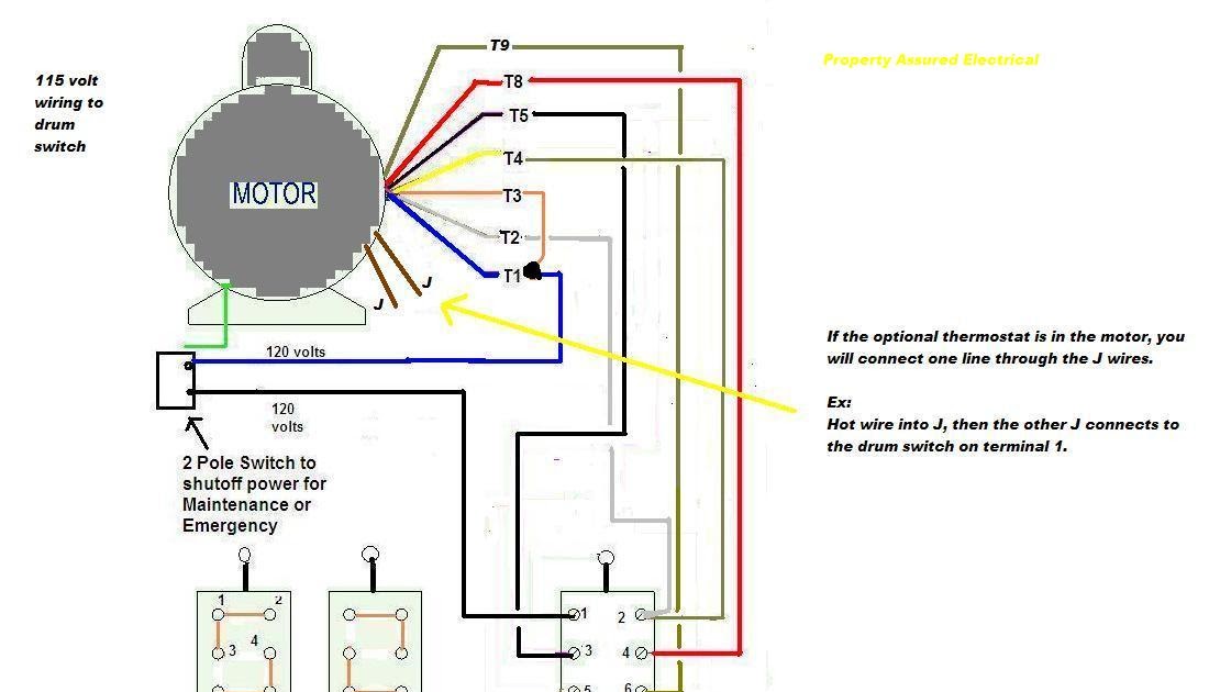
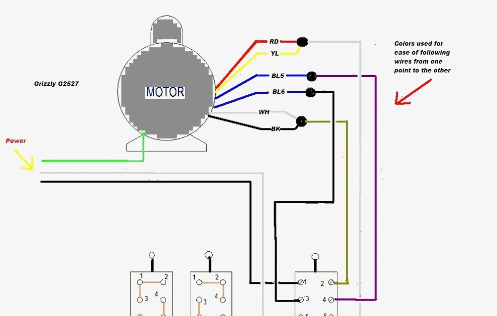
A 120 Volt Dayton Motor Wiring Schematic illustrates the electrical wiring connections necessary to operate a Dayton brand electric motor rated for 120-volt power. It provides a visual representation of the motor’s electrical terminals, their corresponding wire colors, and the proper connection sequence for single-phase power.
Understanding and following the correct wiring schematic are crucial for ensuring the safe and efficient operation of the motor. It helps electricians, technicians, and DIY enthusiasts connect the motor to a power source, motor controller, or other electrical components properly. The schematic provides clear instructions on identifying the motor’s power leads, ground wire, and any additional terminals or accessories.
The 120 Volt Dayton Motor Wiring Schematic has significant relevance in industrial, commercial, and residential settings where Dayton motors are used to power various equipment, appliances, and machinery. It enables the proper installation and maintenance of these motors, ensuring optimal performance and preventing electrical hazards or damage to the equipment. Additionally, the development of standardized wiring schematics has played a key role in streamlining the installation process, reducing errors, and improving safety in electrical systems.
The term “120 Volt Dayton Motor Wiring Schematic” comprises three main parts of speech: a noun (“schematic”), an adjective (“Dayton”), and a noun phrase (“120 Volt”). Understanding these parts of speech is crucial to comprehending the essential aspects of the topic and creating informative content that effectively explores its various dimensions.
- Schematic: A diagram representing the electrical connections of a device or system, in this case, a 120-volt Dayton motor.
- Dayton: Refers to the Dayton brand, a manufacturer of electric motors and other electrical equipment.
- 120 Volt: Indicates the voltage rating of the motor, which is 120 volts.
- Electrical Connections: The schematic illustrates the proper electrical connections required to operate the motor.
- Wiring Diagram: It provides a visual representation of the motor’s electrical terminals and wire connections.
- Single-Phase Power: The schematic is specific to motors designed for single-phase power.
- Safety and Efficiency: Following the correct wiring schematic is essential for ensuring the safe and efficient operation of the motor.
- Electrical Hazards: Improper wiring can lead to electrical hazards or damage to the motor.
These key aspects highlight the importance of understanding and using the 120 Volt Dayton Motor Wiring Schematic correctly. It is a crucial document for electricians, technicians, and DIY enthusiasts to ensure the proper installation and maintenance of Dayton motors. By exploring these aspects further, we gain a deeper understanding of the role of wiring schematics in electrical systems and their significance in ensuring safety, efficiency, and optimal performance.
Schematic
Within the context of “120 Volt Dayton Motor Wiring Schematic”, the schematic serves as a crucial component, providing a visual representation of the electrical connections necessary for the proper operation of the motor. This diagram plays a vital role in ensuring safety, efficiency, and optimal performance.
-
Motor Terminals
The schematic illustrates the various terminals on the motor, including power leads, ground wire, and additional terminals for accessories or control devices. Proper identification of these terminals is essential for making the correct electrical connections. -
Wire Colors and Connections
The schematic specifies the color coding of wires and the sequence in which they should be connected to the motor terminals. Following the designated color scheme and connection order is critical to prevent electrical hazards and ensure proper motor operation. -
Single-Phase Power
The schematic is specific to motors designed for single-phase power. It provides clear instructions on connecting the motor to a single-phase power source, ensuring the correct flow of electricity and preventing damage to the motor. -
Safety and Troubleshooting
The schematic serves as a valuable tool for troubleshooting electrical issues related to the motor. By comparing the actual wiring connections to the schematic, electricians and technicians can identify and rectify any discrepancies, ensuring the safe and efficient operation of the motor.
In summary, the schematic component of “120 Volt Dayton Motor Wiring Schematic” plays a crucial role in guiding the proper installation and maintenance of Dayton motors. It provides a clear visual representation of the electrical connections, ensuring safety, efficiency, and optimal performance. This schematic serves as an invaluable resource for electricians, technicians, and DIY enthusiasts, enabling them to confidently work with Dayton motors and ensure their reliable operation.
Dayton
Within the context of “120 Volt Dayton Motor Wiring Schematic”, Dayton holds a pivotal position as the manufacturer of the specific motor in question. This connection is significant because it establishes the compatibility of the wiring schematic with Dayton motors. The schematic is meticulously designed to match the electrical characteristics and terminal configurations of Dayton motors, ensuring proper operation and adherence to safety standards.
The presence of “Dayton” in the schematic’s title is not merely a brand reference but a critical indicator of its intended application. By specifying Dayton, the schematic conveys that it is specifically tailored to the electrical requirements of Dayton motors, providing precise instructions for connecting and operating these motors.
Real-life examples of “Dayton: Refers to the Dayton brand, a manufacturer of electric motors and other electrical equipment.” within “120 Volt Dayton Motor Wiring Schematic” can be found in various industrial, commercial, and residential settings. Dayton motors are widely used in applications such as pumps, fans, compressors, conveyors, and other machinery. When technicians or DIY enthusiasts encounter a 120-volt Dayton motor, they can confidently refer to the “120 Volt Dayton Motor Wiring Schematic” to guide their installation and maintenance tasks.
Understanding the connection between “Dayton: Refers to the Dayton brand, a manufacturer of electric motors and other electrical equipment.” and “120 Volt Dayton Motor Wiring Schematic” is crucial for several reasons. Firstly, it prevents misuse of the schematic with incompatible motors, ensuring safety and preventing damage to equipment. Secondly, it enables users to make informed decisions when selecting motors and wiring schematics, ensuring compatibility and optimal performance. Thirdly, it contributes to a deeper understanding of electrical systems and the importance of using appropriate components for specific applications.
120 Volt
Within the context of “120 Volt Dayton Motor Wiring Schematic”, the voltage rating plays a crucial role in determining the compatibility and safety of the electrical connections. The “120 Volt” specification in the schematic indicates that it is specifically designed for motors rated at 120 volts. This voltage rating is a critical component of the schematic because it ensures that the instructions and diagrams provided are appropriate for the intended motor.
Real-life examples of “120 Volt: Indicates the voltage rating of the motor, which is 120 volts.” within “120 Volt Dayton Motor Wiring Schematic” can be found in various applications where 120-volt Dayton motors are used. These applications include:
- Residential appliances such as refrigerators, washing machines, and dryers
- Commercial equipment like fans, pumps, and compressors
- Industrial machinery, including conveyors and packaging equipment
Understanding the connection between “120 Volt: Indicates the voltage rating of the motor, which is 120 volts.” and “120 Volt Dayton Motor Wiring Schematic” is crucial for several reasons. Firstly, it prevents incorrect wiring of motors, which can lead to electrical hazards, damage to the motor, or even personal injury. Secondly, it enables users to select the appropriate wiring schematic for their specific motor, ensuring compatibility and optimal performance. Thirdly, it contributes to a deeper understanding of electrical systems and the importance of matching components based on voltage ratings.
In summary, the “120 Volt: Indicates the voltage rating of the motor, which is 120 volts.” specification in the “120 Volt Dayton Motor Wiring Schematic” is a critical component that ensures safety, compatibility, and optimal performance when working with Dayton motors. Understanding this connection is essential for electricians, technicians, and DIY enthusiasts to ensure the reliable and efficient operation of electrical systems.
Electrical Connections
The connection between “Electrical Connections: The schematic illustrates the proper electrical connections required to operate the motor.” and “120 Volt Dayton Motor Wiring Schematic” is crucial, as the schematic provides detailed instructions on how to make the correct electrical connections to operate a 120-volt Dayton motor safely and efficiently.
The schematic serves as a step-by-step guide, illustrating the proper sequence for connecting power leads, ground wires, and any additional terminals or accessories to the motor. Following these instructions carefully is essential to ensure that the motor operates as intended, avoiding potential electrical hazards or damage to the motor or connected equipment.
Real-life examples of “Electrical Connections: The schematic illustrates the proper electrical connections required to operate the motor.” within “120 Volt Dayton Motor Wiring Schematic” are numerous and can be found in various applications where Dayton motors are used. These include residential appliances, commercial equipment, and industrial machinery.
Understanding the electrical connections and following the schematic correctly is critical for various reasons. Firstly, it ensures the safe and reliable operation of the motor, preventing electrical hazards and potential accidents. Secondly, it helps achieve optimal motor performance by ensuring proper power supply and efficient energy utilization. Thirdly, it simplifies troubleshooting and maintenance procedures, enabling technicians to quickly identify and resolve any electrical issues.
In summary, the “Electrical Connections: The schematic illustrates the proper electrical connections required to operate the motor.” component of the “120 Volt Dayton Motor Wiring Schematic” plays a vital role in ensuring the safe, efficient, and reliable operation of Dayton motors. Understanding this connection and adhering to the provided instructions are essential for electrical professionals and DIY enthusiasts to ensure successful installation, maintenance, and operation of Dayton motors in various applications.
Wiring Diagram
The connection between “Wiring Diagram: It provides a visual representation of the motor’s electrical terminals and wire connections.” and “120 Volt Dayton Motor Wiring Schematic” is crucial, as the wiring diagram forms the core of the schematic, providing a clear and detailed guide for making the necessary electrical connections to operate the motor safely and efficiently.
The wiring diagram serves as a visual blueprint, illustrating the layout of the motor’s electrical terminals and the correct sequence for connecting power leads, ground wires, and any additional terminals or accessories. It eliminates guesswork and minimizes the risk of incorrect connections, which could lead to electrical hazards or damage to the motor.
Real-life examples of “Wiring Diagram: It provides a visual representation of the motor’s electrical terminals and wire connections.” within “120 Volt Dayton Motor Wiring Schematic” are numerous and can be found in various applications where Dayton motors are used. These include residential appliances such as refrigerators, washing machines, and dryers; commercial equipment like fans, pumps, and compressors; and industrial machinery, including conveyors and packaging equipment.
Understanding the wiring diagram and following it precisely is critical for several reasons. Firstly, it ensures the safe and reliable operation of the motor, preventing electrical hazards and potential accidents. Secondly, it helps achieve optimal motor performance by ensuring proper power supply and efficient energy utilization. Thirdly, it simplifies troubleshooting and maintenance procedures, enabling technicians to quickly identify and resolve any electrical issues.
In summary, the “Wiring Diagram: It provides a visual representation of the motor’s electrical terminals and wire connections.” component of the “120 Volt Dayton Motor Wiring Schematic” plays a vital role in ensuring the safe, efficient, and reliable operation of Dayton motors. Understanding this connection and adhering to the provided wiring diagram are essential for electrical professionals and DIY enthusiasts to ensure successful installation, maintenance, and operation of Dayton motors in various applications.
Single-Phase Power
The connection between “Single-Phase Power: The schematic is specific to motors designed for single-phase power.” and “120 Volt Dayton Motor Wiring Schematic” is significant because the schematic provides detailed instructions for connecting and operating Dayton motors designed to run on single-phase power. Single-phase power is a common type of electrical power distribution system used in residential and commercial buildings, making it essential to have a wiring schematic specific to motors compatible with this power source.
The schematic serves as a critical component of the “120 Volt Dayton Motor Wiring Schematic” as it ensures the safe and efficient operation of Dayton motors in single-phase power systems. By providing clear instructions on connecting the motor’s power leads, grounding, and any additional terminals, the schematic helps prevent electrical hazards, motor damage, and performance issues.
Real-life examples of “Single-Phase Power: The schematic is specific to motors designed for single-phase power.” within “120 Volt Dayton Motor Wiring Schematic” can be found in various applications where Dayton motors are used with single-phase power. These include residential appliances such as refrigerators, washing machines, and dryers; commercial equipment like fans, pumps, and compressors; and industrial machinery, including conveyors and packaging equipment.
Understanding the importance of single-phase power and using the appropriate wiring schematic is crucial for several reasons. Firstly, it ensures the safe and reliable operation of Dayton motors, preventing electrical hazards and potential accidents. Secondly, it helps achieve optimal motor performance by ensuring proper power supply and efficient energy utilization. Thirdly, it simplifies troubleshooting and maintenance procedures, enabling technicians to quickly identify and resolve any electrical issues.
In summary, the “Single-Phase Power: The schematic is specific to motors designed for single-phase power.” component of the “120 Volt Dayton Motor Wiring Schematic” plays a vital role in ensuring the safe, efficient, and reliable operation of Dayton motors. Understanding this connection and adhering to the provided instructions are essential for electrical professionals and DIY enthusiasts to ensure successful installation, maintenance, and operation of Dayton motors in various single-phase power applications.
Safety and Efficiency
The connection between “Safety and Efficiency: Following the correct wiring schematic is essential for ensuring the safe and efficient operation of the motor.” and “120 Volt Dayton Motor Wiring Schematic” is critical because the schematic provides detailed instructions on how to make the correct electrical connections to operate a 120-volt Dayton motor safely and efficiently, preventing potential electrical hazards, damage to the motor, and accidents.
Incorrect wiring can lead to various safety issues, including electrical shocks, short circuits, and fires. By following the correct wiring schematic, electricians and technicians can ensure that the motor is properly grounded, the power leads are connected securely, and any additional terminals or accessories are wired correctly. This helps prevent electrical hazards and ensures the safe operation of the motor.
Following the correct wiring schematic also contributes to the efficient operation of the motor. Proper wiring ensures that the motor receives the correct voltage and amperage, allowing it to operate at its optimal performance. This results in increased energy efficiency, reduced operating costs, and a longer lifespan for the motor.
Real-life examples of “Safety and Efficiency: Following the correct wiring schematic is essential for ensuring the safe and efficient operation of the motor.” within “120 Volt Dayton Motor Wiring Schematic” can be found in various applications where Dayton motors are used. For instance, in residential appliances like refrigerators and washing machines, proper wiring is crucial to prevent electrical shocks and ensure efficient energy consumption. In commercial settings, such as in pumps and compressors, correct wiring is essential to maintain safe operation and minimize downtime.
Understanding this connection is crucial for electrical professionals and DIY enthusiasts alike. By following the correct wiring schematic, they can ensure the safe and efficient operation of Dayton motors in various applications, preventing accidents, minimizing energy consumption, and extending the lifespan of the motor.
Electrical Hazards
The connection between “Electrical Hazards: Improper wiring can lead to electrical hazards or damage to the motor.” and “120 Volt Dayton Motor Wiring Schematic” is critical, as the schematic provides detailed instructions on how to make the correct electrical connections to operate a 120-volt Dayton motor safely and efficiently, preventing potential electrical hazards, damage to the motor, and accidents.
Incorrect wiring can lead to various safety issues, including electrical shocks, short circuits, and fires. By following the correct wiring schematic, electricians and technicians can ensure that the motor is properly grounded, the power leads are connected securely, and any additional terminals or accessories are wired correctly. This helps prevent electrical hazards and ensures the safe operation of the motor.
Real-life examples of “Electrical Hazards: Improper wiring can lead to electrical hazards or damage to the motor.” within “120 Volt Dayton Motor Wiring Schematic” can be found in various applications where Dayton motors are used. For instance, in residential appliances like refrigerators and washing machines, proper wiring is crucial to prevent electrical shocks and ensure efficient energy consumption. In commercial settings, such as in pumps and compressors, correct wiring is essential to maintain safe operation and minimize downtime.
Understanding this connection is crucial for electrical professionals and DIY enthusiasts alike. By following the correct wiring schematic, they can ensure the safe and efficient operation of Dayton motors in various applications, preventing accidents, minimizing energy consumption, and extending the lifespan of the motor.


Related Posts


