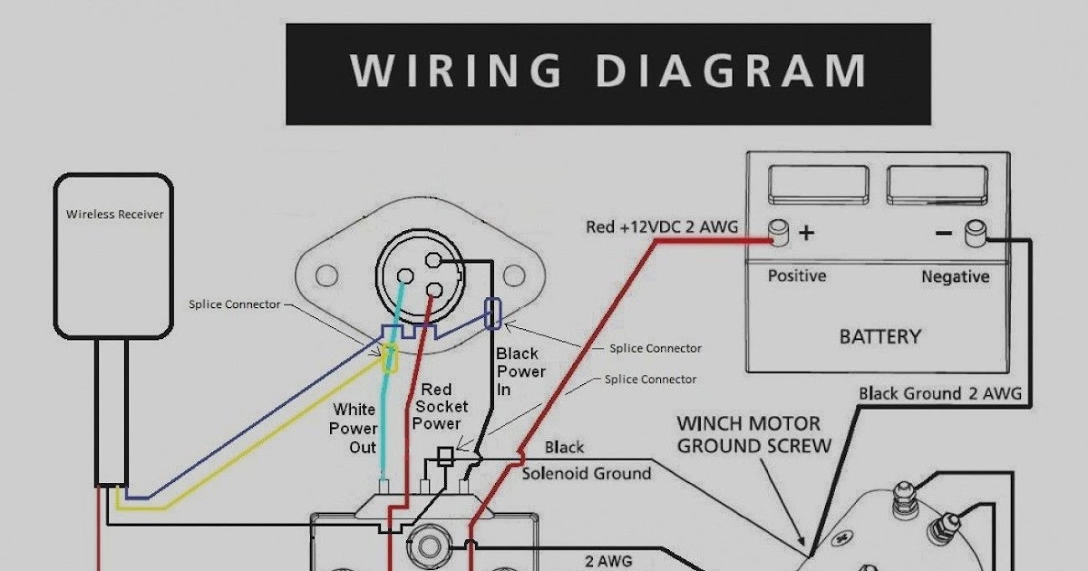
A 12 Volt Winch Wiring Diagram is a schematic representation of the electrical connections required to power and operate a 12 Volt winch. It outlines the wiring connections between the winch, battery, solenoid, and other electrical components, providing a visual guide for proper installation.
Understanding and following a 12 Volt Winch Wiring Diagram is crucial for ensuring safe and efficient winch operation. It helps avoid potential electrical hazards, prevents damage to the winch and its components, and optimizes winch performance. The evolution of winching technology, particularly the introduction of solenoids, has significantly enhanced winch functionality and facilitated easier and more reliable wiring.
In this article, we will delve into the detailed intricacies of a 12 Volt Winch Wiring Diagram, exploring its various components, their functions, and the importance of proper wiring practices. We will provide a comprehensive overview, catering to both novice and experienced users, ensuring a thorough understanding and practical implementation of winch wiring.
To effectively understand and implement a 12 Volt Winch Wiring Diagram, it is imperative to explore its essential aspects. These aspects serve as the building blocks of the diagram, providing a comprehensive framework for understanding its functionality and practical application.
- Components: Relays, solenoids, contactors, switches
- Connections: Wiring, terminals, connectors
- Circuit: Power flow, grounding
- Safety: Fuses, circuit breakers
- Control: Remote, switches
- Layout: Physical arrangement, space optimization
- Troubleshooting: Identifying and resolving faults
- Maintenance: Inspection, cleaning, lubrication
Understanding these aspects allows for a deeper comprehension of the 12 Volt Winch Wiring Diagram. It provides insights into the selection of appropriate components, the establishment of secure connections, and the optimization of the electrical circuit. Furthermore, it emphasizes the significance of safety measures, control mechanisms, and proper layout for efficient winch operation. Additionally, it highlights the importance of troubleshooting techniques and regular maintenance practices to ensure longevity and reliable performance.
Components
In the context of a 12 Volt Winch Wiring Diagram, components such as relays, solenoids, contactors, and switches play crucial roles in controlling the flow of electricity and ensuring the proper functioning of the winch. These components act as electrical intermediaries, enabling the winch to be operated safely and efficiently.
-
Relays
Relays are electromagnetic switches that use a small electrical current to control a larger electrical current. In a winch wiring diagram, relays are used to activate the winch’s solenoid or contactor, which in turn powers the winch motor.
-
Solenoids
Solenoids are electromagnetic coils that create a magnetic field when energized. This magnetic field is used to move a plunger, which can be used to engage or disengage the winch’s gears.
-
Contactors
Contactors are heavy-duty switches that are used to handle high electrical currents. In a winch wiring diagram, contactors are used to connect the winch motor to the battery.
-
Switches
Switches are used to manually control the flow of electricity in a winch wiring diagram. They can be used to turn the winch on or off, or to change the direction of the winch’s rotation.
Understanding the function and proper wiring of these components is crucial for ensuring the safe and reliable operation of a 12 Volt winch. By correctly identifying and connecting these components, users can minimize the risk of electrical hazards and maximize the performance of their winch.
Connections
In the context of a 12 Volt Winch Wiring Diagram, the physical connections between components play a critical role in ensuring the proper functioning of the winch. These connections include wiring, terminals, and connectors, which provide the necessary pathways for electrical current to flow and allow for the control and operation of the winch.
Wiring serves as the conductive medium through which electricity travels. It is essential to select the appropriate wire gauge and type to handle the electrical current requirements of the winch. Terminals provide secure and reliable points of contact between wires and other components, such as solenoids, contactors, and switches. Connectors allow for easy and convenient connection and disconnection of components, facilitating maintenance and troubleshooting.
Understanding the proper wiring, terminals, and connectors to use in a 12 Volt Winch Wiring Diagram is crucial for ensuring safe and efficient winch operation. Incorrect wiring or loose connections can lead to electrical hazards, such as shorts or fires, and can compromise the performance of the winch. By carefully following the wiring diagram and using high-quality components, users can ensure that their winch is properly connected and reliably.
Circuit
In the context of a 12 Volt Winch Wiring Diagram, the circuit, power flow, and grounding play a crucial role in ensuring the safe and efficient operation of the winch. Understanding the relationship between these elements is essential for proper installation, maintenance, and troubleshooting.
The circuit provides the pathway for electrical current to flow from the battery to the winch motor and back. The power flow refers to the direction and magnitude of the electrical current as it travels through the circuit. Grounding provides a reference point for the electrical system and ensures that any stray electrical current is safely discharged.
In a 12 Volt Winch Wiring Diagram, the circuit is typically represented by a series of lines connecting the battery, solenoid, contactor, winch motor, and ground. Arrows are used to indicate the direction of power flow. Grounding is typically achieved by connecting a wire from the negative terminal of the battery to the frame of the winch or to a dedicated grounding point.
Understanding the circuit, power flow, and grounding is essential for troubleshooting electrical problems with a winch. By following the wiring diagram and checking for proper connections, it is possible to identify and resolve issues such as loose connections, faulty components, or incorrect grounding.
In summary, the circuit, power flow, and grounding are critical components of a 12 Volt Winch Wiring Diagram. Proper understanding and implementation of these elements ensure the safe and reliable operation of the winch.
Safety
In the context of a 12 Volt Winch Wiring Diagram, safety measures are paramount to prevent electrical hazards and ensure reliable winch operation. Fuses and circuit breakers play a crucial role in safeguarding the electrical system and protecting against potential damage or injury.
-
Fuses
Fuses are sacrificial devices designed to break the circuit and prevent excessive current flow in the event of an electrical fault or overload. They are typically rated for a specific amperage and will blow when the current exceeds that rating.
-
Circuit breakers
Circuit breakers are reusable devices that automatically trip and interrupt the circuit when an overcurrent condition occurs. They can be reset once the fault is cleared, eliminating the need to replace the fuse.
-
Proper sizing
Selecting the appropriate fuse or circuit breaker size is critical. Undersized devices may not provide adequate protection, while oversized devices may not trip quickly enough to prevent damage.
-
Placement
Fuses and circuit breakers should be placed in easily accessible locations for quick identification and replacement if necessary.
In conclusion, the inclusion of fuses and circuit breakers in a 12 Volt Winch Wiring Diagram is essential for ensuring the safety and reliability of the winch system. By preventing excessive current flow and providing a means of quickly interrupting the circuit in the event of a fault, these safety devices protect the winch, the electrical system, and the user from potential hazards.
Control
Within the context of a 12 Volt Winch Wiring Diagram, “Control: Remote, switches” encompasses the components and mechanisms responsible for operating the winch. Understanding and implementing these control elements are crucial for safe and efficient winch operation.
-
Remote control
A remote control unit allows for wireless operation of the winch, providing convenience and safety, especially in situations where direct access to the winch is limited or hazardous.
-
Wired switch
A wired switch, typically mounted on the winch or nearby, offers a simple and reliable method of controlling the winch’s operation. It provides a direct connection between the operator and the winch.
-
Toggle switch
A toggle switch, often used in conjunction with a remote control, provides an alternative wired control option. Its momentary or maintained operation allows for precise control of the winch.
-
Foot pedal
A foot pedal offers hands-free control of the winch, useful in situations where the operator’s hands are with other tasks or when operating the winch from a distance.
These control components provide versatility and flexibility in winch operation. By understanding their functions and proper wiring, users can optimize the control configuration to suit their specific needs and applications.
Layout
In the context of a 12 Volt Winch Wiring Diagram, layout and physical arrangement play a critical role in ensuring the proper functioning, safety, and efficiency of the winch system. Understanding the relationship between layout and wiring is essential for maximizing the performance and longevity of the winch.
The layout of the winch components, including the motor, solenoid, contactor, and control devices, should be carefully planned to optimize space while ensuring easy access for maintenance and troubleshooting. Proper spacing between components allows for adequate airflow, preventing overheating and potential damage. Additionally, a well-organized layout simplifies the wiring process, reducing the risk of tangles or crossed wires, which can lead to electrical hazards.
Real-life examples of layout optimization in 12 Volt Winch Wiring Diagrams include the strategic placement of the solenoid and contactor near the battery to minimize voltage drop and maximize power delivery to the winch motor. Remote control receivers and wireless switches can be mounted in convenient locations, allowing for safe and efficient operation from a distance. Additionally, weatherproofing and corrosion resistance should be considered when selecting components and designing the layout to ensure long-term reliability in harsh environments.
Understanding the importance of layout in 12 Volt Winch Wiring Diagrams enables users to make informed decisions regarding component placement and wiring strategies. By optimizing the physical arrangement, users can enhance the overall performance, safety, and durability of their winch systems.
Troubleshooting
In the context of “12 Volt Winch Wiring Diagram”, troubleshooting is a crucial aspect that ensures the proper functioning, safety, and longevity of the winch system. It involves identifying and resolving faults that may arise during installation, operation, or maintenance of the winch.
-
Electrical continuity testing
Using a multimeter to check for continuity along the electrical circuit can help identify broken wires, loose connections, or faulty components.
-
Voltage drop analysis
Measuring voltage drop across various components, such as the solenoid, contactor, and motor, can indicate potential resistance or power loss issues.
-
Ground fault detection
Testing for proper grounding connections ensures that stray electrical current is safely discharged, preventing electrical hazards.
-
Load testing
Applying a load to the winch and monitoring its performance can reveal any underlying issues with the motor, gears, or braking system.
Understanding the principles of troubleshooting and applying these techniques empower users to diagnose and resolve common faults in their winch systems. By identifying and addressing these issues promptly, users can minimize downtime, enhance safety, and extend the lifespan of their winches.
Maintenance
Within the realm of “12 Volt Winch Wiring Diagram”, “Maintenance: Inspection, cleaning, lubrication” emerges as an indispensable aspect, pivotal in ensuring the optimal performance, longevity, and safety of the winch system. Neglecting these maintenance practices can lead to premature component failure, diminished efficiency, and potential hazards.
-
Electrical Connections Inspection
Regularly inspecting electrical connections, including terminals, wires, and connectors, for signs of corrosion, loose fittings, or damage can prevent electrical faults, power loss, and overheating issues.
-
Solenoid and Contactor Cleaning
Accumulation of dirt, dust, and debris on the solenoid and contactor can hinder their proper operation. Cleaning these components ensures reliable electrical contact, prevents overheating, and extends their lifespan.
-
Motor Lubrication
Lubricating the winch motor according to the manufacturer’s recommendations reduces friction, minimizes wear and tear, and enhances the motor’s efficiency and lifespan.
-
Gearbox Inspection and Lubrication
Periodically inspecting the gearbox for leaks, wear, or damage, and replenishing the lubricant ensures smooth gear operation, reduces noise, and prevents premature failure.
By adhering to a comprehensive maintenance routine that incorporates “Inspection, cleaning, lubrication”, users can proactively address potential issues, mitigate the risk of breakdowns, and maximize the performance and longevity of their 12 Volt winch systems.


![[DIAGRAM] Momentary Rocker Switches 12v Winch Wire Diagram MYDIAGRAM](https://i0.wp.com/www.teryxforums.net/attachments/how/22305d1431005084-rocker-switch-help-image.jpg?w=665&ssl=1)

Related Posts


