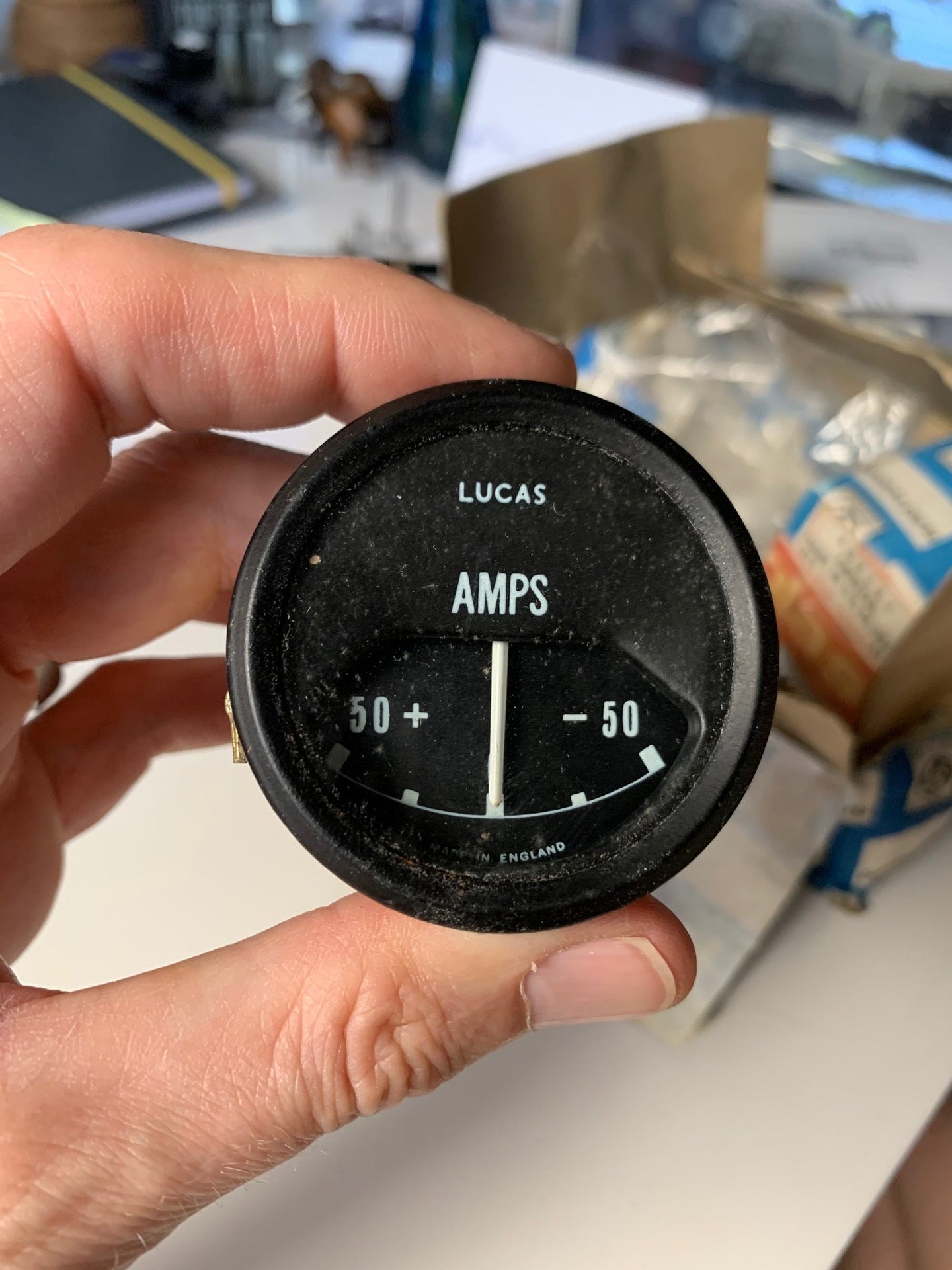
A “12 Volt Amp Meter Wiring Diagram” illustrates the proper connections for an ammeter in a 12-volt electrical system. It shows the flow of electrical current from the battery, through the ammeter, and to the electrical components in the system. By measuring the electrical current, an ammeter provides valuable information about the system’s power consumption and can help diagnose potential problems.
Wiring diagrams are essential for ensuring proper and safe electrical connections. They provide a clear and concise representation of the system’s components and their interconnections. Using a wiring diagram, technicians can efficiently troubleshoot and repair electrical systems, minimizing downtime and ensuring optimal performance.
The development of standardized wiring diagrams played a crucial role in the widespread adoption and reliability of electrical systems. They establish a common language for electrical professionals, allowing them to collaborate effectively and maintain systems across different applications. This has significantly contributed to the safety, efficiency, and reliability of electrical systems in various industries.
The term “12 Volt Amp Meter Wiring Diagram” encompasses several key aspects that are crucial for understanding its function and significance in electrical systems. Identifying the part of speech of the keyword, which is “Noun”, helps us explore these aspects in detail.
- Circuit Diagram: A 12 Volt Amp Meter Wiring Diagram is a specific type of circuit diagram that provides instructions on how to connect an ammeter within a 12-volt electrical system.
- Electrical Current Measurement: The primary purpose of an ammeter is to measure electrical current flowing through a circuit, typically expressed in amps.
- System Monitoring: By monitoring electrical current, the wiring diagram enables technicians to assess the power consumption and overall health of the system.
- Troubleshooting: Wiring diagrams are invaluable for troubleshooting electrical issues, as they provide a visual representation of the system’s components and their interconnections.
- Safety: Properly following the wiring diagram ensures safe electrical connections, minimizing the risk of short circuits or damage to components.
- Standardization: Wiring diagrams adhere to standardized symbols and conventions, allowing for clear communication and collaboration among electrical professionals.
- Efficiency: Using a wiring diagram streamlines the installation and maintenance of electrical systems, saving time and resources.
- Reliability: Accurate and detailed wiring diagrams enhance the reliability of electrical systems by ensuring proper connections and preventing potential problems.
Understanding these key aspects provides a comprehensive understanding of the role and significance of 12 Volt Amp Meter Wiring Diagrams in electrical systems. They are essential for ensuring proper installation, monitoring, troubleshooting, and maintenance, contributing to the overall safety, efficiency, and reliability of electrical systems.
Circuit Diagram
Within the realm of “12 Volt Amp Meter Wiring Diagram”, the aspect of “Circuit Diagram” holds significant importance. It establishes the framework for understanding how an ammeter is integrated into a 12-volt electrical system.
- Components: A circuit diagram for a 12-volt amp meter typically includes symbols representing the ammeter, battery, loads, and connecting wires, providing a visual representation of the system’s components.
- Connections: The diagram specifies the precise connection points for the ammeter within the circuit, ensuring proper current measurement and preventing incorrect or unsafe connections.
- Real-Life Examples: Circuit diagrams for 12-volt amp meters find practical application in various settings, such as automotive electrical systems, battery charging circuits, and solar panel installations.
- Implications: Accurate circuit diagrams are crucial for troubleshooting and maintenance, enabling technicians to identify and rectify issues efficiently, ensuring optimal system performance and safety.
In summary, the circuit diagram aspect of “12 Volt Amp Meter Wiring Diagram” provides a structured and comprehensive guide for connecting an ammeter within a 12-volt electrical system. It outlines the necessary components, specifies the connection points, and serves as a valuable tool for troubleshooting and maintenance, underscoring its critical role in ensuring the proper functioning and safety of electrical systems.
Electrical Current Measurement
Understanding the electrical current measurement aspect is paramount in grasping the significance of a “12 Volt Amp Meter Wiring Diagram.” This measurement provides crucial insights into the behavior and health of an electrical system, allowing for informed decision-making and proactive maintenance.
- Cause and Effect: Electrical current measurement is the driving force behind the wiring diagram’s design. The diagram outlines the specific connections and components necessary to accurately measure the current flowing through the circuit.
- Critical Component: The ability to measure electrical current is a critical component of any electrical system. It enables monitoring of power consumption, detection of overloads, and assessment of component performance.
- Real-Life Examples: In a 12-volt automotive electrical system, an ammeter wiring diagram guides the placement of the ammeter to monitor the current draw of various components, such as lights, ignition, and charging systems.
- Practical Applications: By understanding the electrical current measurement aspect, technicians can interpret wiring diagrams effectively, troubleshoot electrical issues efficiently, and ensure the safe and optimal operation of electrical systems.
In summary, the connection between “Electrical Current Measurement: The primary purpose of an ammeter is to measure electrical current flowing through a circuit, typically expressed in amps.” and “12 Volt Amp Meter Wiring Diagram” lies in the critical role of current measurement in electrical systems. The wiring diagram provides a roadmap for accurately measuring current, enabling monitoring, troubleshooting, and maintenance, ultimately contributing to the safety, efficiency, and reliability of electrical systems.
System Monitoring
Within the context of “12 Volt Amp Meter Wiring Diagram,” the aspect of “System Monitoring” plays a pivotal role. It underscores the critical connection between measuring electrical current and evaluating the performance and integrity of an electrical system.
The ability to monitor electrical current is a fundamental aspect of any electrical system. By providing a visual representation of the current flow, the wiring diagram empowers technicians to assess various parameters, including power consumption, load distribution, and component performance.
Real-life examples of system monitoring within the realm of “12 Volt Amp Meter Wiring Diagram” are abundant. In automotive electrical systems, an ammeter wiring diagram enables technicians to monitor the current draw of different components, such as the starter motor, alternator, and battery, allowing them to identify potential issues and ensure optimal system performance.
The practical applications of understanding system monitoring are far-reaching. It enables proactive maintenance, reduces downtime, and enhances the overall safety and reliability of electrical systems. By monitoring electrical current, technicians can detect anomalies, identify potential problems, and take timely corrective actions, preventing catastrophic failures and ensuring uninterrupted operation.
In summary, the connection between “System Monitoring: By monitoring electrical current, the wiring diagram enables technicians to assess the power consumption and overall health of the system.” and “12 Volt Amp Meter Wiring Diagram” lies in the fundamental role of current measurement in electrical system maintenance. The wiring diagram provides a roadmap for effectively monitoring electrical current, enabling technicians to assess system performance, troubleshoot issues, and ensure the safe and efficient operation of electrical systems.
Troubleshooting
Within the landscape of “12 Volt Amp Meter Wiring Diagram,” troubleshooting electrical issues emerges as a crucial aspect. Wiring diagrams, acting as visual guides to electrical systems, play an indispensable role in identifying and rectifying faults, ensuring optimal system performance and safety.
- Identifying Potential Problems: Wiring diagrams empower technicians to pinpoint potential issues within electrical systems. By studying the diagram, they can anticipate potential failure points and take proactive measures to prevent system downtime.
- Real-Life Examples: In the context of “12 Volt Amp Meter Wiring Diagram,” troubleshooting electrical issues using wiring diagrams is evident in automotive electrical systems. Technicians rely on ammeter wiring diagrams to identify problems related to battery charging, starter motor operation, and electrical accessory malfunctions.
- Implications for System Reliability: Effective troubleshooting using wiring diagrams directly translates to enhanced system reliability. By identifying and resolving electrical issues promptly, technicians can minimize the risk of catastrophic failures and ensure uninterrupted system operation.
- Comparison to Manual Troubleshooting: Wiring diagrams offer a significant advantage over manual troubleshooting methods. They provide a comprehensive overview of the system’s components and their interconnections, enabling technicians to identify issues more efficiently and accurately.
In conclusion, the significance of troubleshooting electrical issues using wiring diagrams cannot be overstated in the context of “12 Volt Amp Meter Wiring Diagram.” Wiring diagrams serve as essential diagnostic tools, empowering technicians to identify and resolve electrical faults, ensuring the safety, efficiency, and reliability of electrical systems.
Safety
Within the realm of “12 Volt Amp Meter Wiring Diagram,” the aspect of safety stands paramount. Adhering to the guidelines outlined in the wiring diagram is crucial for ensuring secure electrical connections, mitigating the potential for short circuits, and safeguarding components from damage. This contributes directly to the overall reliability and longevity of electrical systems.
- Proper Installation: Wiring diagrams provide detailed instructions on how to correctly install electrical components, ensuring secure connections and preventing loose wires that could lead to short circuits.
- Component Protection: By following the wiring diagram, technicians can avoid overloading circuits and damaging sensitive components. The diagram specifies the appropriate current ratings for each component, preventing excessive current flow that could cause overheating and failure.
- Real-Life Examples: In automotive electrical systems, improper wiring can result in blown fuses, damaged alternators, or even electrical fires. Wiring diagrams guide technicians in connecting components correctly, safeguarding against these hazards.
- Compliance with Standards: Wiring diagrams adhere to established electrical codes and standards, ensuring compliance with safety regulations and minimizing the risk of electrical accidents.
In summary, the emphasis on safety in “12 Volt Amp Meter Wiring Diagram” underscores the critical role of proper installation and maintenance in preventing electrical hazards. By following the guidelines outlined in the wiring diagram, technicians can ensure safe and reliable operation of electrical systems, protecting both equipment and personnel from potential harm.
Standardization
Within the context of “12 Volt Amp Meter Wiring Diagram,” standardization emerges as a cornerstone for ensuring clarity, consistency, and effective collaboration among electrical professionals. Wiring diagrams employ standardized symbols and conventions, establishing a common language that transcends individual interpretations and facilitates seamless communication.
- Universal Symbols: Wiring diagrams utilize universally recognized symbols to represent electrical components, such as batteries, resistors, and transistors. This shared visual vocabulary eliminates ambiguity and enables technicians from diverse backgrounds to interpret diagrams effortlessly.
- Consistent Conventions: Wiring diagrams adhere to well-defined conventions regarding line styles, colors, and annotations. These conventions ensure consistency in the representation of electrical connections, making it easier to trace circuits and identify potential issues.
- Real-Life Examples: In the realm of “12 Volt Amp Meter Wiring Diagram,” standardization is evident in the widespread adoption of symbols and conventions defined by international standards, such as those established by the Institute of Electrical and Electronics Engineers (IEEE).
- Collaborative Advantages: Standardization fosters collaboration by providing a common platform for electrical professionals to share and understand wiring diagrams. This shared understanding reduces errors, improves communication, and streamlines troubleshooting processes.
In conclusion, the standardization of wiring diagrams, as exemplified in “12 Volt Amp Meter Wiring Diagram,” plays a critical role in enhancing communication, promoting collaboration, and ensuring the safe and efficient operation of electrical systems. By adhering to standardized symbols and conventions, electrical professionals can effectively convey complex technical information, troubleshoot issues, and maintain electrical systems with confidence and precision.
Efficiency
Within the realm of “12 Volt Amp Meter Wiring Diagram,” efficiency emerges as a crucial aspect, as wiring diagrams play a pivotal role in optimizing the installation and maintenance processes of electrical systems, leading to significant time and resource savings.
- Planning and Preparation: Wiring diagrams provide a comprehensive roadmap for electrical installations, enabling technicians to plan and prepare the necessary materials and components in advance. This eliminates guesswork and reduces the risk of errors, saving time and minimizing wasted resources.
- Simplified Troubleshooting: Wiring diagrams serve as invaluable tools for troubleshooting electrical issues. By providing a visual representation of the system’s components and their interconnections, technicians can quickly identify and isolate faults, reducing downtime and the need for extensive troubleshooting efforts.
- Real-Life Examples: In the context of “12 Volt Amp Meter Wiring Diagram,” the efficiency benefits are evident in automotive electrical systems. Wiring diagrams guide technicians in efficiently installing and maintaining electrical components, such as batteries, alternators, and lighting systems, minimizing vehicle downtime and repair costs.
- Reduced Labor Costs: The streamlined installation and maintenance processes enabled by wiring diagrams directly translate to reduced labor costs. Technicians can complete tasks more quickly and accurately, leading to savings on labor expenses.
In summary, the efficiency aspect of “12 Volt Amp Meter Wiring Diagram” underscores the critical role of wiring diagrams in optimizing electrical system installations and maintenance. By providing a clear visual guide, wiring diagrams save time, reduce resource consumption, simplify troubleshooting, and minimize labor costs, contributing to the overall efficiency and cost-effectiveness of electrical system management.
Reliability
Within the context of “12 Volt Amp Meter Wiring Diagram”, the aspect of reliability takes center stage. Accurate and detailed wiring diagrams play a critical role in ensuring the proper functioning and longevity of electrical systems by providing a precise guide for electrical connections and preventing potential issues that could lead to system failures.
- Precise Connections: Accurate wiring diagrams eliminate guesswork and ensure that electrical components are connected correctly, reducing the likelihood of loose connections, short circuits, and other electrical hazards.
- Prevention of Overloads: Detailed wiring diagrams specify the appropriate current ratings for each component, preventing circuit overloads that could damage components or lead to system failures.
- Real-Life Example: In automotive electrical systems, proper wiring is essential for reliable operation. A 12 Volt Amp Meter Wiring Diagram guides technicians in connecting components like batteries, alternators, and lighting systems, ensuring optimal performance and preventing electrical issues.
- Reduced Maintenance Costs: By ensuring proper connections and preventing potential problems, accurate wiring diagrams contribute to reduced maintenance costs over the lifespan of an electrical system.
In summary, the “Reliability: Accurate and detailed wiring diagrams enhance the reliability of electrical systems by ensuring proper connections and preventing potential problems.” aspect of “12 Volt Amp Meter Wiring Diagram” underscores the critical role of precise wiring instructions in ensuring the safe, efficient, and reliable operation of electrical systems. Accurate wiring diagrams empower technicians to create robust electrical connections, preventing system failures, minimizing maintenance costs, and extending the lifespan of electrical equipment.


Related Posts


