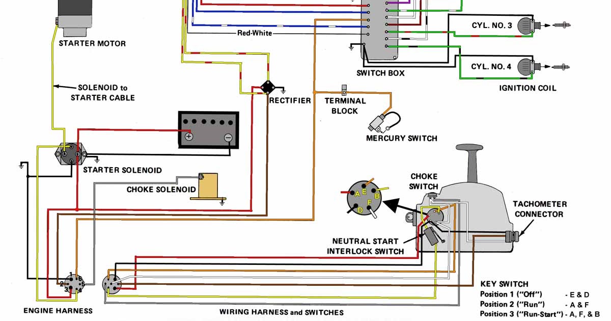
A 115 Hp Mercury Outboard Wiring Diagram is a detailed plan that shows the electrical connections within a 115 horsepower Mercury outboard motor. It provides a visual representation of the wiring system, including the location of components, the flow of electrical current, and the connections between different parts of the motor.
A wiring diagram is essential for troubleshooting electrical problems, performing maintenance, and ensuring the safe and efficient operation of the outboard motor. It allows technicians and boat owners to trace the path of electrical current through the system, identify faulty components, and make repairs. The diagram also serves as a reference for proper installation and maintenance of the motor.
One key historical development in outboard motor wiring was the introduction of computerized engine management systems. These systems use computer-controlled sensors and actuators to monitor and adjust the engine’s performance, including ignition timing, fuel delivery, and throttle position. As a result, the wiring diagrams for modern outboard motors have become more complex, requiring specialized knowledge to interpret and troubleshoot.
Understanding the essential aspects of a 115 Hp Mercury Outboard Wiring Diagram is crucial for ensuring the safe and efficient operation of the motor. As a noun, “115 Hp Mercury Outboard Wiring Diagram” represents a plan that visually depicts the electrical connections within the motor. This diagram serves as a valuable tool for troubleshooting, maintenance, and installation.
- Components: The diagram identifies the location and function of various electrical components, such as the battery, starter, alternator, and ignition system.
- Wiring: It shows the path of electrical wires throughout the motor, including their color coding and gauge.
- Connections: The diagram illustrates the connections between different components, including terminals, connectors, and switches.
- Grounding: It indicates the grounding points for the electrical system, which are essential for safety and proper operation.
- Troubleshooting: The diagram helps technicians identify potential electrical problems by tracing the flow of current through the system.
- Maintenance: It provides a reference for regular maintenance tasks, such as checking connections and replacing faulty components.
- Installation: The diagram guides the proper installation of the outboard motor and its electrical system.
- Safety: Understanding the wiring diagram is essential for ensuring the safe operation of the motor, as it helps identify potential hazards and electrical faults.
- Performance: The diagram can assist in optimizing the performance of the motor by ensuring that all electrical components are functioning properly.
- Compliance: The diagram helps ensure that the electrical system meets industry standards and regulations for safety and reliability.
In conclusion, the key aspects of a 115 Hp Mercury Outboard Wiring Diagram provide a comprehensive understanding of the motor’s electrical system. This diagram is essential for troubleshooting, maintenance, installation, and ensuring the safe and efficient operation of the outboard motor.
Components
Within the context of a 115 Hp Mercury Outboard Wiring Diagram, the identification of electrical components and their functions is paramount for understanding the motor’s electrical system. The diagram serves as a visual guide, pinpointing the location of each component and providing insights into its specific role.
- Battery: The battery is the heart of the electrical system, providing power to start the engine and run the various electrical components. The diagram indicates the location and terminals of the battery, ensuring proper connections and maintenance.
- Starter: The starter motor is responsible for cranking the engine and initiating the combustion process. The diagram shows the location of the starter and its connections to the battery and ignition system, enabling troubleshooting and maintenance.
- Alternator: The alternator generates electricity while the engine is running, recharging the battery and powering the electrical components. The diagram illustrates the location and connections of the alternator, aiding in diagnosing charging issues.
- Ignition system: The ignition system provides the spark necessary for combustion. The diagram identifies the components of the ignition system, including the ignition coil, spark plugs, and wiring, facilitating diagnosis and repair of ignition problems.
Understanding the location and function of these key electrical components through the wiring diagram is essential for troubleshooting electrical faults, performing maintenance, and ensuring the safe and reliable operation of the 115 Hp Mercury outboard motor.
Wiring
Within the context of the 115 Hp Mercury Outboard Wiring Diagram, the depiction of wiring plays a crucial role in understanding the electrical system’s layout and functionality. This aspect of the diagram provides valuable insights into the following key facets:
- Wire Types and Color Coding: The diagram identifies the different types of electrical wires used throughout the motor, each with a specific color coding to denote its function. This color coding is standardized, allowing technicians to easily trace wires and identify their purpose, simplifying troubleshooting and maintenance.
- Wire Gauge: The diagram also specifies the gauge or thickness of each wire. Wire gauge determines the current-carrying capacity of the wire, which is essential for ensuring proper operation and preventing overheating or electrical faults. Understanding wire gauge helps technicians select the appropriate replacement wires during repairs or modifications.
- Wiring Harness: The diagram shows how individual wires are bundled together into a wiring harness, which organizes and protects the wires from damage. The harness simplifies the installation and maintenance of the electrical system, as it allows for easy removal and replacement of components.
- Grounding: The diagram indicates the grounding points for the electrical system. Proper grounding is crucial for safety and ensures that electrical current is safely discharged to the boat’s hull. The diagram helps technicians identify and maintain proper grounding connections to prevent electrical hazards.
Overall, the wiring aspect of the 115 Hp Mercury Outboard Wiring Diagram is a critical component for understanding the electrical system’s design and functionality. It provides essential information for troubleshooting, maintenance, and ensuring the safe and reliable operation of the outboard motor.
Connections
Within the context of the 115 Hp Mercury Outboard Wiring Diagram, the depiction of connections between different components is a critical aspect for understanding the electrical system’s functionality and ensuring its safe and reliable operation.
The diagram illustrates the connections between various electrical components, including terminals, connectors, and switches, which play vital roles in the overall performance of the outboard motor:
- Terminals: Terminals are points of electrical connection, typically made of conductive metal, and provide a secure and reliable interface for wires to connect to components. The diagram specifies the type of terminals used, their location, and the proper method of connecting wires to ensure a strong electrical connection.
- Connectors: Connectors are devices that join two or more electrical wires or components. The diagram identifies the types of connectors used, their location, and the correct procedure for connecting and disconnecting them. Proper connection and maintenance of connectors are crucial to prevent electrical faults and ensure optimal performance.
- Switches: Switches are electrical devices that control the flow of current in a circuit. The diagram indicates the location and function of various switches, such as the ignition switch, kill switch, and trim switch. Understanding the connections and proper operation of these switches is essential for safe and efficient operation of the outboard motor.
By providing a detailed representation of the connections between different components, the 115 Hp Mercury Outboard Wiring Diagram serves as an invaluable tool for troubleshooting electrical problems, performing maintenance, and ensuring the safe and reliable operation of the outboard motor. It empowers technicians and boat owners with the knowledge to identify and resolve electrical issues, prevent malfunctions, and maintain the optimal performance of their outboard motor.
Grounding
Within the context of a 115 Hp Mercury Outboard Wiring Diagram, grounding plays a crucial role in ensuring the safe and reliable operation of the outboard motor. Grounding refers to the intentional connection of an electrical circuit to the metal hull of the boat, which serves as a common reference point for electrical potential.
The 115 Hp Mercury Outboard Wiring Diagram provides detailed information about the grounding points within the electrical system. These grounding points are strategically placed to establish a low-resistance path for electrical current to return to the negative terminal of the battery. Proper grounding is essential for several reasons:
- Safety: Grounding provides a safe path for stray electrical currents to dissipate, preventing the buildup of dangerous voltages on the boat’s hull or other components. This reduces the risk of electrical shocks and potential fires.
- Electrical System Stability: Grounding ensures a stable electrical reference point, which is critical for the proper functioning of electrical components. Without proper grounding, electrical circuits may experience voltage fluctuations and malfunctions.
- Corrosion Protection: Grounding helps protect against corrosion by providing a path for stray electrical currents to flow away from sensitive components. Corrosion can damage electrical connections and lead to premature failure of components.
The 115 Hp Mercury Outboard Wiring Diagram clearly indicates the location and connections of grounding points throughout the electrical system. This information is invaluable for troubleshooting electrical problems, performing maintenance, and ensuring the safe and efficient operation of the outboard motor.
Troubleshooting
Within the context of a “115 Hp Mercury Outboard Wiring Diagram”, troubleshooting plays a critical role in identifying and resolving electrical issues. The diagram provides a visual representation of the electrical system, allowing technicians to trace the flow of current and pinpoint potential problems.
- Circuit Analysis: The diagram enables technicians to analyze individual circuits, tracing the path of current from the power source to the load. By examining voltage readings and continuity, they can identify open circuits, short circuits, and other electrical faults.
- Component Testing: The diagram provides insights into the connections and functionality of individual components. Technicians can use the diagram to test components such as switches, relays, and sensors, verifying their proper operation and identifying any faulty parts.
- Ground Fault Detection: The diagram helps technicians locate ground faults, which occur when an electrical current escapes from its intended path and flows through the boat’s hull or other unintended paths. Ground faults can be hazardous and can lead to electrical shocks or damage to equipment.
- Intermittent Fault Diagnosis: The diagram assists in diagnosing intermittent faults, which are electrical problems that occur sporadically. By studying the wiring diagram, technicians can identify potential sources of intermittent faults, such as loose connections or damaged wires, and develop strategies to resolve them.
In conclusion, the “Troubleshooting: The diagram helps technicians identify potential electrical problems by tracing the flow of current through the system” aspect of a “115 Hp Mercury Outboard Wiring Diagram” is essential for maintaining the safe and reliable operation of the outboard motor. The diagram provides a valuable tool for technicians to diagnose and resolve electrical issues, ensuring the outboard motor performs at its optimal level.
Maintenance
Within the context of the “115 Hp Mercury Outboard Wiring Diagram”, maintenance takes on paramount importance in ensuring the outboard motor’s optimal performance, reliability, and longevity. The diagram serves as a comprehensive guide for carrying out routine maintenance tasks, enabling boat owners and technicians to maintain the electrical system in pristine condition.
- Connection Inspection: The wiring diagram provides a detailed layout of all electrical connections, enabling technicians to visually inspect each connection for signs of corrosion, loose terminals, or damaged wires. Regular inspection and maintenance of connections prevent electrical faults, ensure proper current flow, and minimize the risk of electrical fires.
- Component Replacement: The diagram identifies and locates every electrical component within the outboard motor. This information is crucial when replacing faulty components, as technicians can accurately identify the correct replacement part and its precise location within the electrical system. Timely replacement of faulty components prevents further damage, ensures optimal performance, and extends the lifespan of the outboard motor.
- Wiring Inspection: The wiring diagram provides a visual representation of the entire wiring harness, allowing technicians to thoroughly inspect the condition of wires for any signs of damage, fraying, or insulation breakdown. Regular inspection and maintenance of wiring prevent electrical shorts, ensure proper signal transmission, and maintain the integrity of the electrical system.
- Grounding Verification: The diagram clearly indicates all grounding points within the electrical system. Grounding is essential for electrical safety and proper functioning of the outboard motor. Regular verification and maintenance of grounding connections ensure that electrical current is safely discharged, preventing electrical shocks and damage to sensitive components.
In conclusion, the “Maintenance: It provides a reference for regular maintenance tasks, such as checking connections and replacing faulty components” aspect of the “115 Hp Mercury Outboard Wiring Diagram” is indispensable for maintaining the outboard motor’s electrical system in optimal condition. By utilizing the diagram for routine maintenance and troubleshooting, boat owners and technicians can proactively address potential issues, prevent costly repairs, and ensure the safe and reliable operation of their outboard motor.
Installation
Within the context of the “115 Hp Mercury Outboard Wiring Diagram”, the “Installation” aspect holds significant importance as it provides comprehensive guidance for the proper installation of the outboard motor and its electrical system. This aspect is crucial for ensuring the safe, reliable, and efficient operation of the outboard motor.
- Electrical Component Integration: The wiring diagram outlines the proper integration of various electrical components, including the battery, starter motor, alternator, ignition system, and control panel. It specifies the correct connections, wire routing, and grounding points to ensure optimal performance and prevent electrical hazards.
- Wiring Harness Installation: The diagram provides detailed instructions for installing the wiring harness, which houses and protects the electrical wires. It indicates the routing of the harness, the location of connectors, and the proper securing methods to prevent damage and ensure reliable electrical connections.
- Outboard Motor Mounting: The wiring diagram includes information on mounting the outboard motor onto the boat’s transom. It specifies the correct mounting bolts, torque specifications, and alignment procedures to ensure secure installation and optimal performance.
- Control System Integration: For outboard motors with remote control systems, the wiring diagram provides guidance on connecting the control cables, throttle linkage, and shift mechanism. It ensures proper synchronization between the control system and the outboard motor for safe and precise operation.
In conclusion, the “Installation: The diagram guides the proper installation of the outboard motor and its electrical system” aspect of the “115 Hp Mercury Outboard Wiring Diagram” is essential for ensuring the successful installation and operation of the outboard motor. By following the detailed instructions provided in the diagram, boat owners and technicians can avoid costly mistakes, prevent potential hazards, and achieve optimal performance from their outboard motor.
Safety
Within the context of a “115 Hp Mercury Outboard Wiring Diagram”, safety takes precedence as it provides crucial information for the safe installation, operation, and maintenance of the outboard motor. Understanding the wiring diagram empowers individuals to identify potential hazards and electrical faults, enabling them to mitigate risks and ensure the well-being of boaters and passengers alike.
- Hazard Identification: The wiring diagram clearly outlines the electrical system’s layout, enabling users to identify potential hazards such as exposed wires, improper connections, and overloaded circuits. This knowledge allows for proactive measures to be taken, such as proper insulation, secure connections, and appropriate fuse ratings, preventing electrical fires and shocks.
- Fault Diagnosis: The diagram provides a systematic approach to diagnosing electrical faults, guiding users through the process of tracing circuits, testing components, and identifying the root cause of problems. This empowers individuals to address electrical issues promptly, minimizing downtime and enhancing the overall reliability of the outboard motor.
- Grounding and Bonding: The wiring diagram emphasizes the importance of proper grounding and bonding, which are essential for electrical safety. It illustrates the connections between the electrical system and the boat’s hull, ensuring that stray currents are safely discharged, preventing the accumulation of hazardous voltages and reducing the risk of shocks.
- Compliance with Regulations: The wiring diagram helps ensure compliance with industry standards and regulations related to electrical safety. By adhering to the recommended practices outlined in the diagram, boat owners and technicians can be confident that the outboard motor’s electrical system meets or exceeds safety requirements, giving them peace of mind.
In conclusion, the “Safety: Understanding the wiring diagram is essential for ensuring the safe operation of the motor, as it helps identify potential hazards and electrical faults” aspect of the “115 Hp Mercury Outboard Wiring Diagram” serves as a vital tool for promoting electrical safety and maintaining the well-being of boaters. By empowering individuals to identify hazards, diagnose faults, implement proper grounding and bonding techniques, and adhere to safety regulations, the wiring diagram contributes to the safe and enjoyable operation of outboard motors.
Performance
Within the realm of “115 Hp Mercury Outboard Wiring Diagram”, understanding the intricate connection between performance and the diagram is paramount. The diagram serves as a comprehensive guide, providing insights into the electrical system’s design, functionality, and impact on the outboard motor’s overall performance.
A properly functioning electrical system is the backbone of optimal outboard motor performance. The wiring diagram empowers individuals to trace electrical circuits, identify potential issues, and ensure that all electrical components are operating at their peak efficiency. By addressing electrical faults, optimizing component performance, and maintaining a stable electrical environment, the diagram contributes directly to enhanced engine responsiveness, improved fuel efficiency, and reliable operation.
Real-life examples abound, showcasing the practical significance of this understanding. Consider a scenario where an outboard motor experiences intermittent starting issues. Armed with the wiring diagram, a technician can systematically troubleshoot the electrical system, pinpoint the faulty component (e.g., a loose connection, failing starter solenoid), and promptly resolve the problem. By restoring the electrical system to its optimal state, the outboard motor regains its reliable starting capability, ensuring a seamless boating experience.
Furthermore, the wiring diagram plays a crucial role in maximizing fuel efficiency. A well-tuned electrical system ensures that the engine receives the appropriate spark timing and fuel mixture, optimizing combustion efficiency. This translates into improved fuel economy, allowing boaters to travel farther on a single tank of fuel.
In summary, the “Performance: The diagram can assist in optimizing the performance of the motor by ensuring that all electrical components are functioning properly” aspect of the “115 Hp Mercury Outboard Wiring Diagram” emphasizes the critical relationship between electrical system integrity and outboard motor performance. By utilizing the diagram to maintain, troubleshoot, and optimize the electrical system, boat owners and technicians can harness the full potential of their outboard motors, ensuring reliable, efficient, and enjoyable boating experiences.
Compliance
Within the context of a “115 Hp Mercury Outboard Wiring Diagram”, compliance with industry standards and regulations plays a pivotal role in ensuring the safety and reliability of the outboard motor’s electrical system. The wiring diagram serves as a valuable tool in achieving and maintaining compliance, providing a comprehensive overview of the electrical system’s design and functionality.
- Adherence to Safety Standards: The wiring diagram ensures adherence to established safety standards, such as those set by the American Boat and Yacht Council (ABYC) and the National Fire Protection Association (NFPA). By following the recommended practices outlined in the diagram, boat owners and technicians can minimize the risk of electrical fires, shocks, and other hazards, safeguarding the well-being of passengers and crew.
- Compatibility with Regulations: The wiring diagram assists in ensuring compatibility with applicable regulations, including those governing the installation and operation of marine electrical systems. By adhering to the guidelines provided in the diagram, boat owners can be confident that their outboard motor’s electrical system meets or exceeds regulatory requirements, avoiding potential legal liabilities and ensuring smooth operation.
- Quality Assurance: The wiring diagram contributes to quality assurance by providing a clear and concise representation of the electrical system’s design. This enables manufacturers, inspectors, and boat owners to verify the system’s accuracy, completeness, and compliance with industry standards. By promoting transparency and accountability, the wiring diagram helps ensure that the outboard motor’s electrical system meets the highest standards of quality and reliability.
- Simplified Troubleshooting: The wiring diagram simplifies troubleshooting efforts in the event of electrical faults or malfunctions. By providing a detailed roadmap of the electrical system, technicians can quickly identify potential problem areas, trace circuits, and diagnose issues with greater accuracy and efficiency. This reduces downtime, minimizes repair costs, and contributes to the overall reliability of the outboard motor.
In conclusion, the “Compliance: The diagram helps ensure that the electrical system meets industry standards and regulations for safety and reliability” aspect of the “115 Hp Mercury Outboard Wiring Diagram” underscores the importance of adhering to established standards and regulations. By utilizing the wiring diagram to design, install, and maintain the outboard motor’s electrical system, boat owners and technicians can be confident that they are operating a safe, reliable, and compliant vessel.

![[47+] Free Mercury Outboard Manuals Online, Mercury Mariner Outboards](https://i0.wp.com/i.pinimg.com/originals/5c/68/e6/5c68e660d9dda6c2d185a2b5971020d7.jpg?w=665&ssl=1)


Related Posts


